- Home
- Product Categories
- LCDs and OLEDs
- Color LCD - Breakout Board

Color LCD - Breakout Board
Replacement:LCD-11062. The new version of this board has a larger inductor to better support screen compatibility. This page is for reference only.
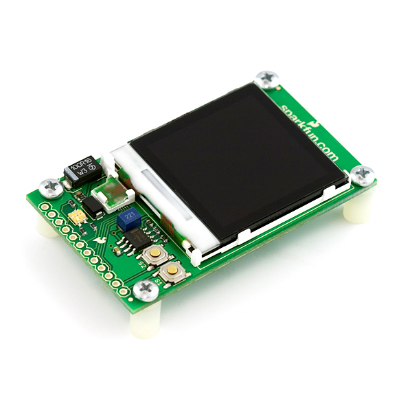
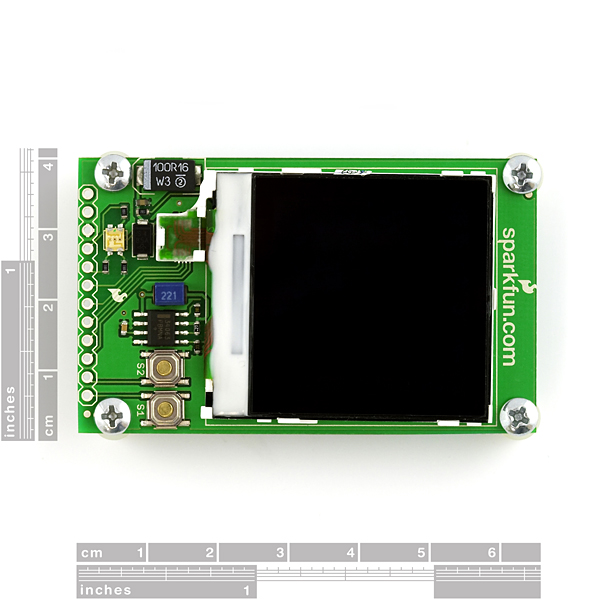
Created for the Sinister 7 Tutorial, this breakout board for the popular Nokia 6100 Knock-off color LCD has an improved backlight driver circuit (boosts to 7V) , plus we give you a tri-color status LED and 2 pushbuttons, all accessed through one 12-pin 0.1" spaced header. Slightly less versatile than the previous version yet slightly more functional, this breakout is set up for serial communication to the display.
This board comes with Nokia 6100 display attached and stand-offs as photographed.
Note: Pins 8 and 9 on the Nokia LCD connector will be connected with a solder bridge.
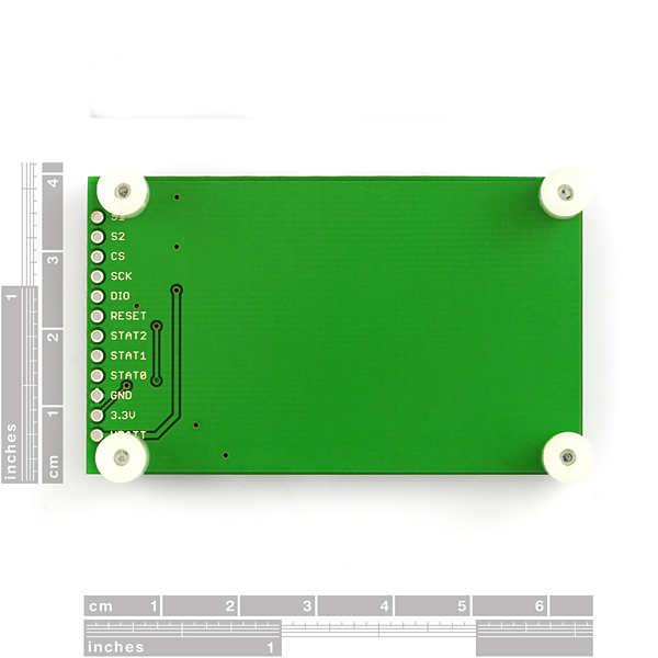
Pin connections:
- +Vbat (backlight driver input)
- 3.3V (logic supply, regulated input)
- Ground
- Stat0 (Red status LED, low active)
- Stat1 (Blue status LED, low active)
- Stat2 (Green status LED, low active)
- Reset
- DIO
- SCK
- CS
- S2 (Pushbutton 2, low active)
S1 (Pushbutton 1, low active)
+Vbat and the 3.3V input can be driven from the same regulated 3.3V source, but the device will draw more current than if the +Vbat input was driven from a higher source voltage. For a given +Vbat input voltage, you can expect the current draw to be:
108mA @ 6V input
- 120mA @ 5V input
- 243mA @ 3.7V input (single Lipo cell)
- 324mA @ 3.3V input
- 1.5"x2.5"
Comments
Looking for answers to technical questions?
We welcome your comments and suggestions below. However, if you are looking for solutions to technical questions please see our Technical Assistance page.
Customer Reviews
No reviews yet.
ARDUINO + NOKIO LCD BREAKOUT BOARD
Got most of it working based on the posts from this forum...http://www.arduino.cc/cgi-bin/yabb2/YaBB.pl?num=1237036119/all.
I used this library...http://elec.tkjweb.dk/blog/wp-content/uploads/NokiaLCD.zip
Please refer to the posts by Phokur to make changes to the .cpp file to get things working. He has suggested changes for the following things(worked for me)...
1- LCD CLEAR FUNCTION
2- COLOR SETTINGS
3- TEXT DRAW FUNCTION
Still working on displaying images.
LCD running in 12bit coulr mode - test pattern: all 4096 colours
Hi, can you please share your pde sketch and schematic? tnx
---Library updated: 22nd Oct 2011---
If anyone is interested, I have created an Arduino Library for this. (I hadn't noticed there was an example library, so i made my own.)
gLCD Library
You just need to copy the gLCD folder inside the zip file to the 'libraries' folder in the directory where arduino is installed.
There are also two example sketches which explain how to use the library. In the Arduino software go to File -> Examples -> gLCD -> BasicFunctions (or TestPattern)
The library works with both Phillips and Epson controllers. It can't yet detect which one you have, so you have to specify that as part of the Init() command. See either example sketch for more information.
At the moment it can draw lines, boxes, and circles. It can plot individual pixels, you can control the colour (4096 colours), and print out text strings. There is also a built in test pattern.
There is also a function to set the contrast of the screen if the default value doesn't work properly.
Data for printing characters is now stored in the program memory, which frees up 480bytes of SRAM.
For phillips displays, the init() call has been changed. It is now:
graphic.Init(xOffset,yOffset,invertColour,1,mirrorX);
-(xOffset,yOffset) sets the position of the origin on the screen in case some pixels are cut off.
-invertColour reveses the colour values when true (i.e. if black appears as white, set this to 1.
-mirrorX reverses the x direction.
This change is due to some phillips displays displaying a mirror image.
I have also added a fast digitalWrite function to the library, which if turned on increases the refresh rate of the screen by a factor of 10.
In order to use this, you must define which port each LCD pin is on in the gLCD.h file. If you use use RS = 8, CS = 9, and Data and Clk on any pin between 10 and 13 inclusive, then the library won't need changing as these are predefined.
To use the faster function this should be defined:
gLCD graphic(RS,CS,CLK,DATA,1);
This is as it was before, except there is a fifth variable, which informs the library to use the fast write.
I will be updating the library slowly, at the moment it is version 1.3
Unfortunately I don't have a PDE as my LCD is controlled by a PIC18F46K20.
However, for a Uni project I am currently porting my PIC code for Arduino, so if you check back in a week or so, I will try to share it when done. :)
Is it possible to get /just/ the board? I have a supply of LCDs with that obnoxiously small connector.
works great using the bit bang, on arduino
has anybody got it to work using the native spi? on the arduino mega?
hey,
why did you include a tri state led, if there is a lcd screen for feedback?
is it now a different revision with a new inductor
Hi everyone,
I got my board a couple of weeks ago.
I'm trying to control the LCD with a PIC18F4550, but so far I managed just to get a blue screen.
I'm using the SPI output of the microcontroller, but I was considering using a software SPI: do you think this would solve?
I think that the problem is related to the way the embedded SPI handles the 9 bit instructions: do you think a software SPI would solve?
Has anyone got it working with a PIC?
Please help me!!!
Finally got mine working several months after i bought it :). Pretty neat display, its just a nightmare to get it to turn on. Im using a PIC18F46K20 (3.3v pic) running at 32MHz to get it going - I have managed to get the SPI link going at around 1MHz without any data loss.
I have however as was suggested above had to put a 22ohm resistor in series with the backlight supply as the inductor gets very very hot otherwise.
Did you use a software SPI or the microcontroller one?
Sorry, I'm a newbie, but why do you need to run the microcontroller at 32 MHz and the SPI at 1? Why so much difference?
Thank you
I am not using the hardware SPI, i am using a software one. To time the SCLK, I am using the C code delay_us(), which is why the most i can get is 1MHz - Also at trying to get higher than those speeds on a peice of Veroboard was causing trouble.
The pic is running at 32MHz as i wanted the instruction cycles to be as short as possible so as not to effect the timing of the clock too much - I had an 8MHz crystal lying around (actually 200 of them as when i bought them i hadn't realised they were sold in packs of 100, DUH). I am then using the HS-PLL to bring it up to 32MHz
The trick to getting the screen to turn on is working out the correct sequence of controlling the LCD. I found the Jim Lynch tutorial linked here http://www.sparkfun.com/products/569 helpful, but a bit still required some tinkering to get it going. This is my startup sequence:
clear_bit(MX_GFXLCD_TRIS, MX_GFXLCD_RS); //Configure I/O
clear_bit(MX_GFXLCD_TRIS, MX_GFXLCD_CS);
clear_bit(MX_GFXLCD_TRIS, MX_GFXLCD_SDATA);
clear_bit(MX_GFXLCD_TRIS, MX_GFXLCD_SCLK);
clear_bit(MX_GFXLCD_PORT, MX_GFXLCD_RS); //Reset LCD
delay_ms(10);
set_bit(MX_GFXLCD_PORT, MX_GFXLCD_RS); //Startup LCD
set_bit(MX_GFXLCD_PORT, MX_GFXLCD_CS); //Select LCD
set_bit(MX_GFXLCD_PORT, MX_GFXLCD_SDATA); //Set Data Pin High
set_bit(MX_GFXLCD_PORT, MX_GFXLCD_SCLK); //Set Clock Pin High
set_bit(MX_GFXLCD_PORT, MX_GFXLCD_RS); //Startup LCD
delay_ms(10); //Wait after Reset
LCD_SendByte(MX_GFXLCD_CMD, 0xCA); //Configure Display
LCD_SendByte(MX_GFXLCD_PARAM, 0x00); //2 divisions, switching period=8 (default)
LCD_SendByte(MX_GFXLCD_PARAM, 0x20); //nlines/4 - 1 = 132/4 - 1 = 32)
LCD_SendByte(MX_GFXLCD_PARAM, 0x00); //no inversely highlighted lines
LCD_SendByte(MX_GFXLCD_CMD, 0xBB); //Common Output Scan (avoid split display)...
LCD_SendByte(MX_GFXLCD_PARAM, 0x01); //...Scan 1->80, 81->160
LCD_SendByte(MX_GFXLCD_CMD, 0xD1); //Enable Oscillators
LCD_SendByte(MX_GFXLCD_CMD, 0x94); //Sleep Out
LCD_SendByte(MX_GFXLCD_CMD, 0x20); //Voltage Regulators On
LCD_SendByte(MX_GFXLCD_PARAM, 0x0F); //Ref voltage, then circuit voltage, then booster
LCD_SendByte(MX_GFXLCD_CMD, 0xA6); //Invert Display
LCD_SendByte(MX_GFXLCD_CMD, 0xBC); //Display Control
LCD_SendByte(MX_GFXLCD_PARAM, 0x03); //Scan direction LCD_SendByte(MX_GFXLCD_PARAM, 0x00); //RGB colour order
LCD_SendByte(MX_GFXLCD_PARAM, 0x02); //colour mode - 4096 colours
LCD_SendByte(MX_GFXLCD_CMD, 0x81); //Contrast Control
LCD_SendByte(MX_GFXLCD_PARAM, 0x2B); //0 to 63: contrast
LCD_SendByte(MX_GFXLCD_PARAM, 0x01);
delay_ms(100); //Allow Power to stablise
LCD_SendByte(MX_GFXLCD_CMD, 0xAF); //Display On
delay_ms(40);
Clear();
where LCD_SendByte(command,data) is calling my SPI send macro "command" is a 1 or a 0 depending on whether the data is a command or a parameter, and the "data" is a byte of data.
I can't get past that dreadful blue screen! I managed to get an old Philips controlled screen to work on this breakout board without any trouble but this new Epson controller is a bit more of a challenge! I'm using an Atmel XMEGA256A3.
What was the trick to get your screen to switch on?
All of you are aware that I'm normally a 5v logic specialist. That also includes the odd display. That can also include the normally odd controller.
But what about attaching that one to an MSP430 type controller? Has anyone gone down that path?
Hi, I bought one of this LCDs, but I can´t make it works. First I dont know which driver use the LCD, so it´s so difficult to work with it... can anybody help me with this problem?
I am using a PIC 18F4550 and the CCS compilator and I am not an expert but I like to experiment with this kind of things, so if anyone knows a way to communicate with the LCD, just to check the communication, I would appreciate your help. Thanks
my mail: camigord@hotmail.com
High-pitched whine?
Anyone experience a high pitched whine when the lcd backlight is on? disconnecting vbatt stops it from happening.
Thanks,
Ali
Yeah, mine does that, a small resistor between the Vbatt and VDD made the whine go away. (I used 22ohm as i had one on hand)
I have my LCD working. Except the power boost inductor gets as hot as the sun. I've tried it at 3.3v, 3.6v and 5v. It got so hot the little blue inductor package is now black instead of blue! And you can't read the 221 anymore. I havent ran it for 5mins straight yet, that cant be right.
I have the red PCB version, just bought it. Anyone else having this kind of heat problem?
Apparently inductor L1 in the schematic (220 uH) is underrated for the current passing through it. See the forum thread at http://forum.sparkfun.com/viewtopic.php?f=15&t=15448 where user "dstahlke" replaced the inductor with one rated for 500 mA and this caused the backlight to work better and also to draw one fifth the current it did previously!
SparkFun, are you going to upgrade the inductor so we don't have to hack it ourselves?
Yep, we know about it. This one's on the list for a revision. Not sure exactly when it's going to get done (just being honest), but it's gonna get done.
Hmm, one year later, and this still isn't fixed?? Just burned my finger at the damn thing.
well, stop touching it...
Hello,
My LCD work, but all color is blue variant, any idea ?
EPSON, 4k color mode
http://aerith.fr/LCD.jpg
- middle square display 4096 color
- bottom : red, yellow, cyan, blue, pink
- bottom : 16 grayscales
Thanks.
Hi Aeris,
contact me at nospam2 at colinmackenzie.net . I notice from your pic that you have the same red PCB as I. We can help each other get this LCD going.
I think you need to adjust contract. I had this prob too. Whatever source code you use, there will be a line about setting the volume. Set this to 45 or so. The blue will go away.
Thanks, I try 45 and is better, the backgound is not black but more color is true.
It's not possible to have real black on this display ?!
For your inductor, I put 5V and is not very hot
Plz, I need the datasheet of my Color LCD - Breakout Board that i shapped it 2 days ago. i need it plz coz i must deliver my graduation project after 2 days. so i need it to now how to interface with it using atmega32.
thx
All information is supplied on the actual LCD's page:
http://www.sparkfun.com/commerce/product_info.php?products_id=569
The 4k colors Type B dont work on mine, I think is not the same. It's a S1D15G10D00 ?...
Does It look like half the dots are missing? You can just make out the image but the pixels are messed up? I had this. Strangly, it worked later when I was not attaching to the Atmel with the debugger. I was also connecting and disconnecting only the VBatt pin while the LCD and atmel was otherwise operating. For some reason, recycling power on the Vbatt pin was changing the pixel modes. (Inducing noise on the serial lines probably.) I had to disconnect Vbatt often because the boost power inductor gets too hot after 30 secs.
eberajas,
How did you connect pic to the lcd? I purchased the PIC 18F4682 but the pins are so small...
Hi,
The break out makes things easy to connect to with some jumper wires. If you aren't already using one, you might want to use a development board to make connections easier.
I ordered this board and i was wondering if there were tutorials for interfacing this lcd with a 16f628a or a 16f84a. anyone?!
Argon: I ordered this board and i was wondering if there were tutorials for interfacing this lcd with a 16f628a or a 16f84a. anyone?!
Check out the page for the LCD, the code examples are there. http://www.sparkfun.com/commerce/product_info.php?products_id=569
That plus the schematic for the breakout board should get you started.
Hello!
Has anyone gotten the device to work with a basic Arduino board? (Your choice, I have the fellow here named after last year.)
Ideally since they do have instructions for using most of the graphic display LCD devices that are sold at Sparkfun, plus the Serial Backpack character ones.....
i have using a seeeduino mega
Any chance of selling just the board without the Nokia LCD? I bought the LCD separate from you guys a few months ago and had no idea how dismally small that little connector was! At the moment, I have no idea how I'm going to connect it to use it.
Is the backlight supposed to come on as soon as you connect VBATT and GND to a suitable supply voltage, or do you need to initialise the display controller over SPI first?
I can't get my LCD to do anything, not even shine the backlight (using an arduino): I've tried various code examples and none of them do anything..
Yes, the backlight should illuminate when you apply power to the VBATT/GND pins. If you have a multimeter, you might measure to see if the voltage boosting circuit is producing 7V.
Is the LCD snuggly seated onto its connector?
Drop us an email, we'd be happy to help.
-techsupport at sparkfun dot com
Hello!
I primarily do my work with TTL logic. Any suggestions on using this breakout board that way?
Can this be used with a Beagle Board?
What would it take to hook this up to a CMOS camera (such as http://www.sparkfun.com/commerce/product_info.php?products_id=8668) and just get a live video feed? I searched the forums and only found information on connecting to a computer. I am looking to build something extremely portable.
Thanks in advance for helping a newbie!
Am I ruining the LCD backlight if I drive VBatt from a 9V?
I just fried my LCD by applying too many volts to VBATT.
I looked up the data sheet for the MC34063 - the 7V regulator. The data sheet says it's a step-up/step-down regulator, and max input is 40v, so I think, hmmm... 15V should be no prob. But I didn't read the whole data sheet (who does?) The MC34063 uses a different layout depending on which function it's being used for. On this board, it's wired as boost (step-up), not step down. Duh!
The LCD backlight came on for a while, then everything went dark...
No eagle files?
It has a EPSON controller and now is working with a PIC 18F4682.
Thanks.
Hi, did you use C code for the PIC?
Thanks
Dear ebarajas;
I am using same LCD with atmega8 but nothing work. if it works with u can u plzz give a little help.if u can give me code or something even it is PIC i can translate it thanxxx.
zai3our@hotmail.com
I bought this LCD board. My concern is:
What controller uses the LCD?
1) Philips PCF8833 Chipset
2) Epson S1D15G10
The LCD is labeled as:
GE128128-ROHS
N. 080724-0034
7168007001 829
K4
Please answer to this concern in order to use properly this LCD display.
"Pins 8 and 9 on the Nokia LCD connector will be connected with a solder bridge."
What does this means? Is this breakout board rady to use?
Probably what it means is that those two pins are supposed to be tied together - and that the way they did it with this board is just by bridging the two pins within the footprint. The reason they mention it is because, if they didn't, then someone might see that solder bridge and think, "oh, that's what's wrong!"
I got the old breakout board but have lost the documentation as well (silly me for thinking online docs will be online forever ;-) Tracing the circuit I got the following:
(pins numbered according to SparkFun's labelling of the last pin on the right as 8)
1. VCC??
2. Backlight Power??
3. #RESET
4. DATA
5. CLOCK
6. #CS
7. Backlight Enable??
8. GND??
Those labeled ?? are the ones I'm guessing. I don't have a dev environment set up right now to test. Can anyone else confirm the functions of pins 1, 2, 7 & 8? Better yer can SparkFun confirm them?
It would be nice if there was an Eagle footprint consisting of the connector and screw holes. I ordered this breakout board and am designing a board to attach it to, but I don't know where to put the holes. When the mail arrives I can just measure it, but it would still be nice to have an Eagle footprint, or at least a copy of the board that I can cut and paste from.
Are the docs for the old breakout board still around? Could you maybe provide a link to the page for the old breakout board, that would be great!