
The PLC
Microcontrollers are everywhere today. They are cheap, relatively fast, and easy to use! Using a current IDE makes programming a breeze; couple that with a decent debugger and programming gets even easier. Most of us, including me, take for granted that we can scroll through hundreds of code lines in a few seconds. Need to locate a variable? Ctrl+F and you'll have all of its locations instantly. That’s a luxury that didn't always exist. I’d like to take a look at an industrial control device, the Programmable Logic Controller (PLC).
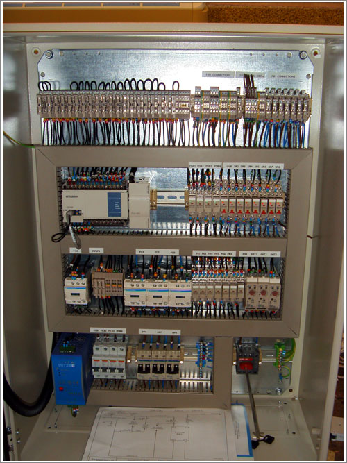
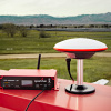
A PLC being used in a industrial application
Now hold on. Before you get your caps lock ready, yes I know PLCs are still used in everything everywhere and can be quite modern. I'm talking about really old PLCs. The ones that didn't interface to a computer and had to be programmed directly from a keypad. The Programmable Logic Controller is a term trademarked by Allen-Bradley (Rockwell Automation). PLCs are often used in industrial settings where extreme variations in temperature, vibrations, electrical noise, and mechanical shock are the norm. Before the PLC, relay logic (along with other non-computerized methods) was used to control machinery. Because a 'program' could number in the thousands of relays, changing a single 'line' of code could be extremely time consuming. In a large installment, timing was also an issue. There is a slight delay while the mechanical portion of the relay moves. Times that by hundreds of relays and you may have issues. This created the demand for a simple, input-output operating system that could be easy to implement and easy to program. So was born the PLC.
My PLC
Aside from a few variations, PLCs are programmed primarily with what is called ladder logic ("It's a ladder!"). It is called ladder logic because it looks like a ladder! Ladder logic executes in a very predictable order, top to bottom, with no function calls or other fancy trickery. Modern PLCs can be programmed using an ethernet or RS cable, but older models had to be programmed from a keypad.
Alright, enough history. What I really want to do is show you my PLC. Let's get started.
I'm going to be showing you my Series One Junior Programmable Logic Controller. This device resided on a shelf in my father's shop until I was old enough to understand how to use it. I can remember looking at an 8 pin socket relay and thinking it looked like the power crystal for a spaceship. I'm not big on leisurely reading, but I could read 200 page instruction manuals all day. So that is what I did. I picked up the manual and read it front to back in order to get a general understanding of how to use this thing. Let's go over some basics.
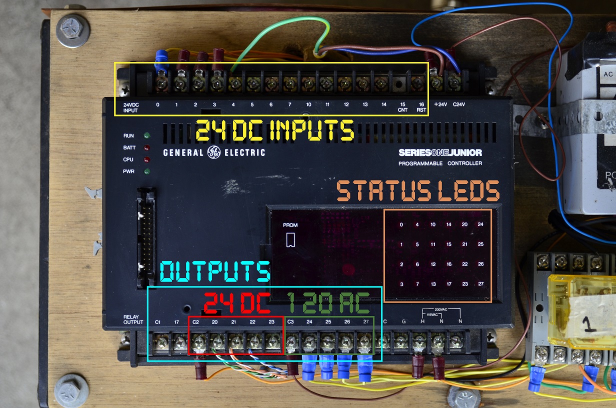
My PLC
The top row is used for 24 VDC inputs. Lots of industrial equipment uses 24 VDC. The bottom terminals are the outputs, the C_ stands for common. So for example, I have 24 VDC connected to terminal C2. When terminal 20,21,22, or 23 is switched ON, it is supplied with 24 VDC. Similarly, C3 supplies terminals 24-27 with 120 VAC. The status LEDs show which inputs are receiving power and which outputs are switched ON. The H and N in the bottom right are the main power to the controller. Finally, the 26 pin connector on the left is where the keypad plugs in.
How about some specifications?
Max of 700 16-bit words, stored in CMOS RAM (needs a battery to retain code)
24 I/O - expandable to 96
2 kHz clock for timing purposes, able to manage 20 simultaneous timers
160 internal coils - think of these as boolean variables with no physical output
155 slots for shift register operations.
The Keypad
The keypad is used to program the controller. It allows the user to monitor a specific set of inputs/outputs and shows the current memory location 0-699.
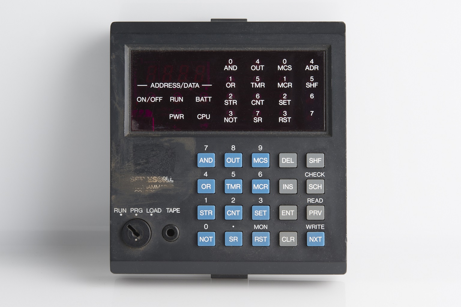
The programming keypad. Looks sort of like a detonator
Let's go over the key functions. I'll be comparing ladder logic to C style programming.
AND - Equal to && - places contacts in series. Works with inputs and outputs.
OR - Equal to || - places contacts in parallel. Works with inputs and outputs.
STR - Starts a new line of logic. Tells the controller that we are about to enter data.
NOT - Equal to ! - inverts the logic. Works with inputs and outputs.
OUT - The action to be performed upon a logic block being true - normally energizes an external contact or internal coil.
TMR - Creates a new timer function to be used.
CNT - Specifies a counter function to end two logic rungs.
SR - Specifies a shift register function to end 3 logic rungs.
MCS/MCR - Master Control Set/Reset - groups many logic lines into one unit which is governed by a single coil, input, or output. Think emergency stop.
SET - Energizes an internal coil, often used for timing.
RST - De-energizes specified SET coils.
DEL/INS - Delete and insert. Used for deleting a line of code or adding one in, pushing everything down one slot in memory.
ENT - Enters the logic into memory.
CLR - Clears user input.
SHF - Shift - allows access to secondary keys labeled in white above the actual key.
SCH - Search - allows user to search for a logic statement such as an input, output, or coil number.
PRV/NXT - Allow monitoring of I/O states, also scrolls through lines of code.
MON - Allows monitoring of ranges of I/O in groups of 8. Statuses are displayed with an LED.
WRITE - Copies the stored logic through the audio port...to a cassette tape! I think that is awesome.
READ - Load code in from a cassette tape.
CHECK - Checks the RAM vs tape for consistency.
RUN - Puts the PLC into normal operation mode. No code changes allowed.
PRG - Program mode. Allows code input and modification.
LOAD - Prepares to read or write code through the audio port.
TAPE - 3.5mm audio jack.
Code Examples
Let's see some ladder logic!
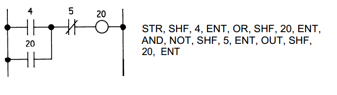
Simple input/output code
Pseudocode: If input 4 or output 20 is energized but not input 5, energize output 20.
if( ( 4 || 20 ) && !5 )
    turn 20 on;
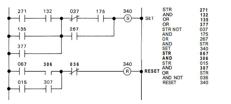
Latching Logic. Coil 340 stays energized until specific conditions de-energize it
Pseudocode: If (271 and 132), or (135), or (377) are energized and not (37 and 175) or 267, then SET 340 to ON. If (67 and 306) or (15 and 307) are energized but not (36), then RESET coil 340.
if( ( (271 && 132 ) || 135 || 377 ) && ( (!37 && 175 ) || 267 )
    SET 340 ON;

if( ( ( 67 && 306 ) || ( 15 && 307 ) ) && !36 )
    RESET coil 340;
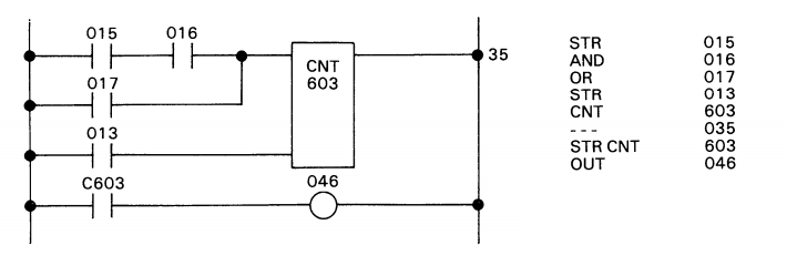
A simple timing diagram that counts to 35
Pseudocode: If (15 and 16) or 17 are toggled, add 1 to 603. If counter 603 reaches 35 counts or more, turn on 46. If 13 is energized then reset timer 603.
POWER = false if 15, 16, and 17 are false. The power to the counter must be toggled in order to increment again.
if( 17 )
    counter 603 = 0;

if( (15 && 16) || 17 && !POWER ) {
    add 1 to 603;
    POWER = true;
}

if( 603 >= 35 )
    turn on 46;

 if( !15 && !16 && !17 )
    POWER = false;
CHALLENGE
Can you determine what this logic does? Go on, I dare you! Now is your chance to shine. Remember: Numbers 0-16 are inputs, numbers 17-96ish are outputs, numbers 160 through 400ish are internal coils - boolean variables that have no physical output, and numbers 600-620ish are timer coils, they keep time. Annnnnnnnnnnnnddddd GO!
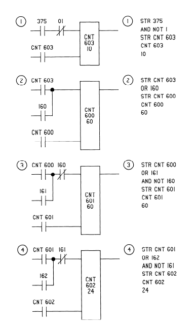
Mystery code. What does it do? No cheating!
Almost done, I promise
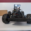
Alright so I have this PLC, a bunch of industrial components, what now? Learning how to use the PLC was one challenge, but the real test was actually doing something with it. I already had most of the parts I needed just sitting around, so I built an aluminum can crusher. Because this post is already running into next week, I'm posting the video, the code, and I'm outta here! Post any questions in the comments below. Oh and thanks for reading this far. Unless you skipped to the end, then boo.
Also, this was filmed 4 years ago. I don't like hearing my own voice so I haven't watched it in 2 years. Don't make fun of me, I am a sensy.
ReplaceMeOpen
ReplaceMeClose

The code/logic for the crusher


Ah yes, PLCs, ladder diagrams and relay logic... Love it. Been messing with the various forms since the 1980's. Used to work for a museum, and was in charge of most of the technical operations, from building HVAC to exhibits. A good deal of the HVAC used PLCs of one form or the other. Actually, one of the biggest PLC installs I saw was when we had rented some of the big traveling lifesize moving Dinosaur exhibits. All pneumatic driven movements, and all the air valve cycling controlled by programs running on PLCs not all that different from the can crusher.
Great article, and thanks for the spotlight on the PLCs. Great Can Crusher too! :) True, PLCs are a cut above pure relay logic and much easier to program, but sometimes I miss the chatter of relays cycling.
True Story: At our museum, back in the 1980's our building elevator was all relay logic driven, much like the octal cube relays on top of the can crusher. There were 3 floors to the building, and on the second floor were some nature dioramas that included a fullsized stuffed moose. Well the moose was across the aisle facing the elevator.
For some reason, once in a blue moon, if you got in on floor 1, and pressed the button for floor 3, the elevator would start up - and even with no call on floor 2 - sometimes the elevator would stop on floor 2. The door would open, no one would be there but you would stare at the moose who was staring at you, and then the door would close and you would continue up to 3.
This was only once in a while, and most times without anyone else even being on the second floor. It was like the stuffed moose would move and sometimes run across the hall and press the button for the elevator. Door would mysteriously open... there was the stuffed moose.... door would close. We wound up calling it "Visiting the Moose" and it was local lore that the stuff moose knows how to work the elevator.
Elevator company could find nothing wrong- all buttons, switches, motors, sensors were working fine. There was a full printout of the relay control logic and wiring at the panel, and yes, it was all in Ladder Diagram. Dozens of relay coils and contact points, buttons, sensors, indicator lights, etc.
I spent a week reading that diagram and following the relay logic, and watching the relays (luckily with indicator lights on each) cycle as the elevator did its thing. I eventually found it. It was a race condition between a set of contacts closing on one relay and the elevator position sensor relay for floor 2. If one relay dropped out just a split second too slow before the other pulled in it created a false "stop at floor 2" condition. Since relays do take a finite amount of time to transition from one state to the other this can indeed cause issues in close timing applications. The fix here was to move 2 wires from the offending relay contacts to a relay that was actually controlled from that relay. The extra few milliseconds delay as one relay cascaded to the next was enough to prevent the race condition and the elevator stopped mysteriously stopping on floor 2.
I still swear the moose moves though while I'm not looking...
24 hour clock with tenths of seconds.
Correct. Nice work.
OK, here's the obvious comment on the video, made by my inner 8-year-old boy...
Have you ever done it with FULL cans of soda? Heh heh heh.
I'll see what I can do this weekend. I haven't turned it on in 2 years because Colorado doesn't like it when you crush your cans. Or something. I don't know, but I was upset when I found out.
Hopefully well shaken cans of soda...I think this idea calls for a follow up video :P
FWIW, y'all might like to know that the video he's posted had a hand in getting Paul hired here, to the tune of "Sweet! Aw, damn, that rocks!"
It makes me want to build one. It is a nicely done project.
Big thing smash can good. Good make big thing.
Did you construct all of the mechanical parts or did you find/modify what you needed from existing components?
I wish I had a Dad with some awesome stuff hanging around. Nice work
The frame was already built, but I made everything else. All the individual electronics and pneumatics were sitting around.
Hey I trained on one like this and I do remember those diagrams for programming the PLC (RETS Electronics). Memories! I haven't used one since.
Love the sound that the air makes as the plunger is retracted. And every project needs a big red button.
Nice build, and nice article. I did an event years (and years) ago, in which I got to program a fully articulated giant dinosaur, using a PLC and only a keypad controller much like the one shown. So time consuming!
Good article! I do control system retrofits for utility generators, thankfully I have not had to extract programming from something that old, yet, most of the time we're adding so many new components it's easier to just redo the program from scratch. You'd be surprised what the electrical grid is running on, I've seen everything from vacuum tubes & pneumatics to fiber optics and modern processing.
I don't think they would care, typically I see these things a few hours before we go in and take it all out. I don't have any on me at the moment, but I will definitely take a few pictures next time I get chance. In the mean time, here's an old analog beast, you can see all the wire wrapping and relays on the door. http://instagram.com/p/aOa-dMA91R/
That looks like a headache to rebuild....
If you guys want some pictures of ancient programming terminals and PLC's, wait til I get to the office tomorrow! I've got some dinsosaurs... And Koyo made (makes) that same PLC for GE/Fanuc, Siemens, Texas Instruments, and PLC/Automation Direct. A 100 Word demo IDE is downloadable free from automationdirect.com. The text language Paul is using is implemented by other older PLC manufacturers, particularly Mitsubishi's early Melsec series. But other manufacturers ASCII interface looked like this "xio bst xic nxb xic bnd xic ote." Extra credit to Paul or anyone else that can translate that to a ladder diagram...
I'll take a crack at your Allen Bradley text logic...
First contact “XIO” = examine if open BST = branch start Second contact after bst “XIC” = examine if closed NXB = next branch Third contact after nxb “XIC” = examine if closed ( Paralleled with the 2nd contact ) BND = branch end Forth contact after bnd “XIC” = examine if closed OTE = Output energized
For some reason I can't paste a picture of the ladder but basically it is a NC contact in series with 2 NO parallel contacts followed by another NO contact in series with the parallel contacts and then the coil... I think
Also, as points of interest, I believe that is a Melsec in Paul's title picture. And please notice the "tape" jack on the programming terminal- that's right, we used to store programs on cassettes.
When I was a kid we didn't have no fancy fang-dangled PLC thingamajig. We wanted to crush cans we just put 'em on the floor and stomped on 'em.
Cool machine though!
http://cubloc.com/product/01_01cb210.php
This is a product that has been out for awhile. The CB210 combines a CUBLOC PLC controller with a USB interface on an "Arduino" format circuit board. Has 1kB available for your ladder logic.
Anyone tried it?
I remember working with a PLC guy to map registers from the PLC over to our DCS (using a serial comm). On our end it took a couple seconds to locate the placeholders for the registers, while it took minutes to find each register in the ladder logic. It was fairly nightmarish.
Fun Fact: The first PLC created ran for 25 years successfully before it finally died out(modicon 084 and was then called a Modular Digital Controller). They used to require their own dedicated industrial computers the size of a small refrigerator.
I designed/prototyped an open-source PLC but didn't think there would ever be any interest in it. Nice to see SF shedding some light on it!
That's really cool to look at where PLC's came from. I work on Beckhoff PLC's myself and it's really amazing where they've come from and the capabilities they've gained over the years.
Nice write-up. I agree with you and the comments of others. A new modern PLC does all the things that most have commented on and more (Hot swap, redundant processors, on-line configuration, etc.) and are truly great machines. But these features have always come with a high price tag. For example, an AB 1756-L61 lists for $6K, and that does not include backplane, com card, power supply, IO and all of the other things that make it work. Granted that this way overkill for the home or hobbyist, you get an idea of cost. The nice thing about some of the modern microcontrollers is that you get some of the great features of the PLC for $10 of dollars verses $100s or even $1000s. Would I use a basic Arduino to run a chemical plant, probably not. But for around the house stuff and simple machines, you betcha!
So that's what a PLC looks like. I always thought they were just microcontrollers, it's sweet to see a bit of the history behind it.
Like dis - for scale, those bolts are 1/4-20s
I think there maybe a mistake in your text.
Pseudocode: If (271 and 135), or (135),
I believe it should read
Pseudocode: If (271 and 132), or (135).
This is a great article very welll written. PLC have always amazed me and I would love to play with one. Unfortunately I don't have the space to set one up. I have a number of designs for implementing one using the arduino boards.
Yep you are correct. I waited until the night before to finish this. I was up a bit late.... Thank you.
Nicely done Paul, If I remember correctly Koyo made basic PLCs for a few manufacturers a while back. GE and PLC Direct were a couple. That is why the software and keypads are the same for the GE Series One Junior and the PLC Direct 305. I had to make a program change recently on a PLC Direct 305 using that same keypad you used, oh boy lots of fun. I'm used to using old DOS or windows ladder logic software. I have an old Allen Bradley PLC 2 rack with a very old heavy programming terminal that comes with it's own CRT built in. I'll think of something to do with it eventually but at the moment I am having too much fun with arduinos, lol.
PS, in your first Timer diagram, Timer 603 is reset on contact 13, not 17, as listed in code and text. ;) PPS. I R Confused. In your Timer and Challenge diagrams, you're calling them CNT. What are they counting? Shouldn't they be TMR? I dunno. Never used that specific PLC.
Good catch, thanks. I believe the difference between the two are that timers use tenths of a second increments 0.1 - 999.9 seconds , and counters just count by 1's 1-9999. Counters also require two rungs of logic, the first rung controls when the counter is incremented and the lower one allows you to reset the counter.
Also, my explanation was incorrect in the first counter diagram - I had been explaining it as if it was a timer, but it is a counter. A timer will continue to count when conditions are met, up to 999.9 seconds. A counter will increment by one when conditions are met, but the conditions must be reset and then met again for the count to increment again.
In the challenge, coil 375 is actually a 10Hz signal generator providing 0.1 second pulses to counter 603. After 10 pulses (1 second_ counter 603 pulses once and resets. That single pulse is sent to counter 600, which keeps track of seconds. As time builds up, the numbers cascade through the rungs until 24 hours have passed at which point it returns to zero.
Sorry for the confusion.
Thanks! Now I understand.
Thanks for the writeup and I so love that can crusher. Bravo!
Sounds like you could have done with some Rockwell Automation Retro Encabulators in there !
https://www.youtube.com/watch?v=TuhYd9L_d7w
Hah! Yea there was one running off screen. It's an older model, but still has the collapsible fluid-operated self-guided flywheel actuator adapter. And really, that's all you need.
What has always surprised me about PLC is that it wasn't too long ago you'd have a closet of these things controlling something fairly simple, and now the cutting edge 16nm FinFET transistors are letting FPGAs do the same thing in a fraction of the size (try in the millimenter scale).
Science and technology is great.
And, quite probably, on the order of millions of times faster.
Hz to MHz (and in some odd cases GHz) yes, millions. Plus more memory!
Sorry to say the GE Series One Junior can be programmed by a computer! Check out AutomationDirect series 305 PLCs.
I know, but I wanted to demonstrate keypad only use. Plus I don't know how.
Many if not most roller-coasters since the 1970s have been controlled by PLCs. Allen-Bradley was involved and pushed to continuously provide faster and higher capacity PLCs for this application area.
Industrial technicians aren't software engineers and in many cases are mechanics. Ladder logic is easily taught to these techs which allows the tech to troubleshoot low to medium complexity problems on their own. The engineer(s) are probably not on-site or even in-country at this point in time.
Pneumatic controls are still heavily used in nuke plant controls due to the slow, expensive process required to qualify any new equipment for that environment. Utilities keep equipment forever, so you'll see a mix of technologies still in-use.
James
Modern "PLC"s have many modern features like ARM processors and such. So while older PLC's follow this, many new models are quite capable with their abilities. In example: I am currently designing a PLC like interface board for a Raspberry Pi. A modern example from National Instruments would be their line of a C-RIO line. They are able to be programmed in languages like Java, C++, and LabView. So while they can still be programmed in a PLC-esque manner, (from labview), they have become much more compact and adaptable.
Sorry! Just wanted to throw it out there for the people who didnt know!
Alright, as long as we're all being friendly.
It's worth a mention that new PLC's are entirely capable, can be fault tolerant and completely redundant, with hot swap modules and redundant fiber optic network and I/O connections. Some have web servers built in and can speak many, many protocols for communication. They're programmed in standard text based languages if need be. It's not fair to give a bad impression of something by using old technology and only giving a one sentence mention to the newer models(which aren't actually too new) that do things well beyond the capabilities of those ancient dinosaurs. I work on Siemens S7-400H systems all day so I may be a bit defensive. But it deserves more a mention then what new PLC's got.
We could go for days about what things can do, this post is about an old PLC. If I wrote a post about an old car and how it didn't have power steering would you suddenly feel like new cars aren't getting the attention they deserve and get defensive because your car has power steering?
Everyone relax, this is just a fun post about a old controller that was fun to blow the dust off and use. Please refer to my original quote if you are still upset.