Why You Should De-Rate Capacitors
Why the voltage rating on capacitors matters and why you should derate them.

ReplaceMeOpen
ReplaceMeClose
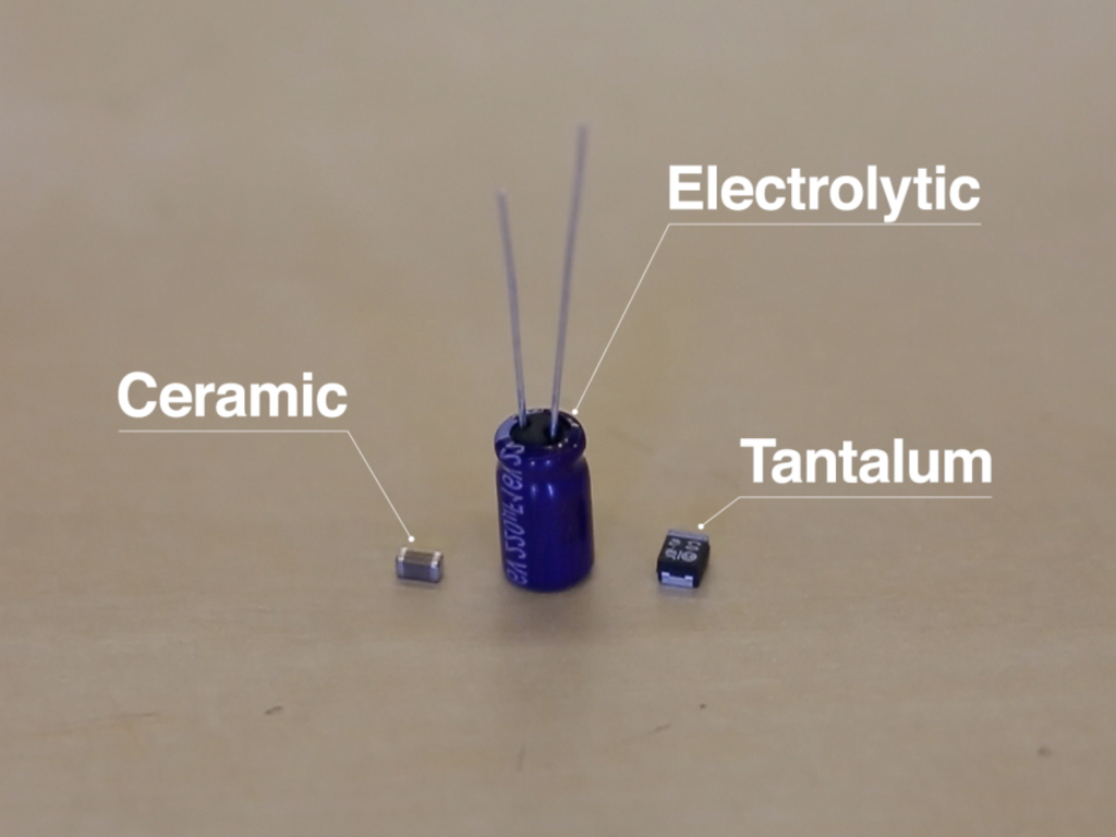
Capacitors Galore
Capacitors are one of the most common elements found in electronics, and they come in a variety of shapes, sizes, and values. There are also many different methods to manufacture a capacitor. As a result, capacitors have a wide array of properties that make some capacitor types better for specific situations. I would like to take three of the most common capacitors - ceramic, electrolytic, and tantalum - and examine their abilities to handle reverse and over-voltage situations. Note: several capacitors were harmed in the making of this post.
Ceramic Capacitors
The most common capacitor is the multi-layer ceramic capacitor (MLCC). These are found on almost every piece of electronics, often in small, surface-mount variants. Ceramic capacitors are produced from alternating layers of metal paste and ceramic powder. These devices are then baked at temperatures in excess of 1200°C in a process called sintering, which fuses the ceramic powder into a solid. Both ends of the capacitors are dipped in metal to connect the alternating plates and provide a solderable surface.
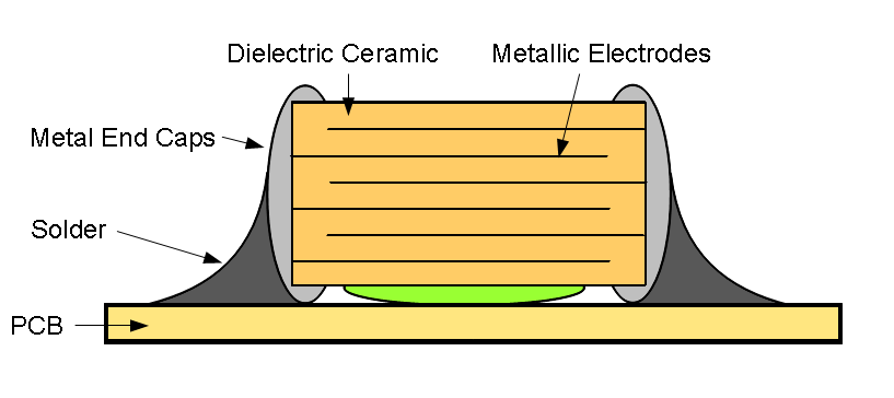
Ceramic capacitor (Image adapted from: http://en.wikipedia.org)
Ceramic capacitors are great for a wide range of uses, including coupling, decoupling, filtering, timing, etc. Since they are non-polarized devices, they can be used in AC circuits. Most ceramic capacitors have a fairly high voltage rating. If the capacitor experiences a voltage between its terminals higher than its rated voltage, the dielectric may break down and electrons will flow between the thin metal layers inside of the capacitor, creating a short. Luckily, most ceramic capacitors are built with a hefty safety margin and do not experience any sort of catastrophic failure (such as exploding). However, the rule of thumb dictates that you should derate ceramic capacitors by 50%, which means that if you are expecting to have a maximum of 5V between the capacitor's leads, then you should use a capacitor rated for 10V or more.
One thing to keep in mind is that ceramic capacitors will lose their capacitance value as the voltage approaches and surpasses the rated voltage. You might see a 10uF capacitor rated for 6.3V become 2uF when 6V is applied to the terminals!
Aluminum Electrolytic Capacitors
Electrolytic capacitors are also very common and are found in the quintessential "can" body. These capacitors are constructed from a piece of paper soaked in electrolyte sandwiched between two pieces of aluminum foil. One piece of foil, the anode, has a coating of aluminum oxide. This coating acts as the dielectric between the two electrodes. The electrolytic paper is electrically conductive, but has chemical properties that allows it to heal the oxide layer should it become damaged. The combination of aluminum oxide dielectric and electrolytes allow for very high capacitance values in a small package. The three layers are rolled together and sealed in a cylindrical aluminum housing.
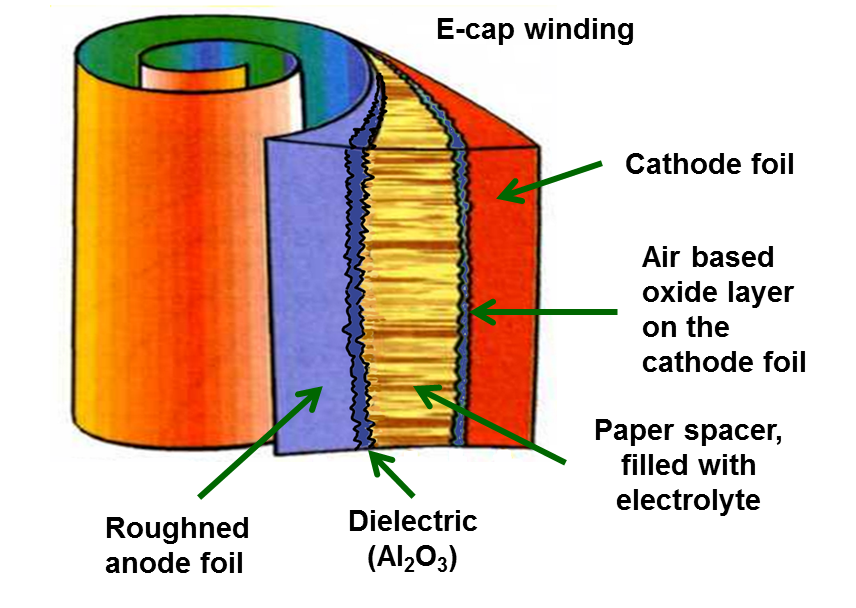
Aluminum electrolytic capacitor (Image credit: http://en.wikipedia.org)
The aluminum oxide layer allows for the flow of current in one direction, which is a problem for capacitors. As a result, electrolytic capacitors cannot be used to couple AC signals. If the capacitor sees a reverse voltage or over-voltage, the aluminum oxide layer breaks down and a short circuit occurs between the electrodes. As current flows through the paper spacer, the electrolyte heats up, often resulting in the capacitor leaking or bursting. Most modern electrolytic capacitors have a seal at the end of the can which cracks open to relieve the built up pressure in the event of a failure. Once this happens, the capacitor is no longer useful, but it will generally fail open.
Tantalum Capacitors
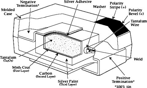
The tantalum capacitors is a special type of electrolytic capacitor. To make a tantalum capacitor, powdered tantalum is formed into a pellet through the sintering process. The pellet is submerged in an acidic solution and a DC voltage is applied, which creates an oxide layer over all the tantalum particles. This oxide layer ultimately forms the dielectric that separates the two electrodes. For the solid tantalum capacitors used in the demonstration, the pellet then receives successive coatings of manganese dioxide, graphite, and silver to form the cathode of the capacitor. This coated pellet is then packaged in a casing with external leads attached to the anode and cathode.

Tantalum capacitor (Image credit: http://www.globalspec.com)
Much like aluminum electrolytic capacitors, tantalum capacitors offer immense capacitance values in very small packages. However, they are even more susceptible to over- and reverse voltage than their aluminum counterparts. With enough voltage, the dielectric breaks down and current begins to flow between the anode and cathode. The current flow can generate a good amount of heat, which can start an exothermic reaction where the tantalum and manganese dioxide act as a type of thermite. Yes, that capacitor, with enough energy, becomes a tiny thermite grenade.
The flame from an exploding tantalum capacitor is usually enough to ruin nearby circuitry. The worst part is that they often fail short. If you are using tantalum capacitors for power supply decoupling and a voltage spike causes a tantalum "event," the power and ground lines are then shorted together, which could ruin even more circuitry. Most literature calls for de-rating tantalum capacitors by 60%-70%. If you must use them, I would suggest de-rating by a lot more than that, such as 33% (e.g. if you are putting a tantalum capacitor on a 5V line, use one rated for 15V or more). In my humble opinion, you would do well to avoid tantalum capacitors all together.
De-Rating Rule of Thumb
While people may argue about what is acceptable for de-rating capacitors, I would suggest using capacitors whose voltage rating is at least 2-3 times that of the expected voltage. For example, if you plan on decoupling a 5V power line, use a capacitor with a rated voltage at 10V or above. I recommend above 3x for tantalum (or better yet, don't use tantalum capacitors at all). Generally, it's a bad day if you see this:


Tantalums have a lot longer lifetime than electrolytics when treated right, though. If you want to build for the next 10 years, not just the next 1 year, consider tants your capacitor of chocie.
This. We would only use ceramics and Tantalums in our space hardware. And even in the thin, dry air we have in Colorado, I've had many problems with electrolytics "drying out" over time. And when you send a piece of equipment to a repair center at a lower, more humid location, it suddenly works again. Unfortunately you can't just replace the ELs with Tantalums since they don't make Tantalums in the large sizes required by power supplies. But they do make much longer-lasting circuits.
Cheapo noname electrolytics spring leaks as well as "dry out". I've had more ham radios, TVs, stereos, etc die from bad electrolytics than anything else (I once paid to have my 27" old-school CRT TV's pizza sized mainboard recapped.) But that's in a 20 year time frame. For the hobbyist, it means don't use old electrolytics you've found in somebody's attic. And for an electrolytic over 10 years years old, test first and expect capacitance to vary 5x or 10x more than spec.
PS: ... and electrolytics usually have a MTBF lifetime specified in their datasheets..
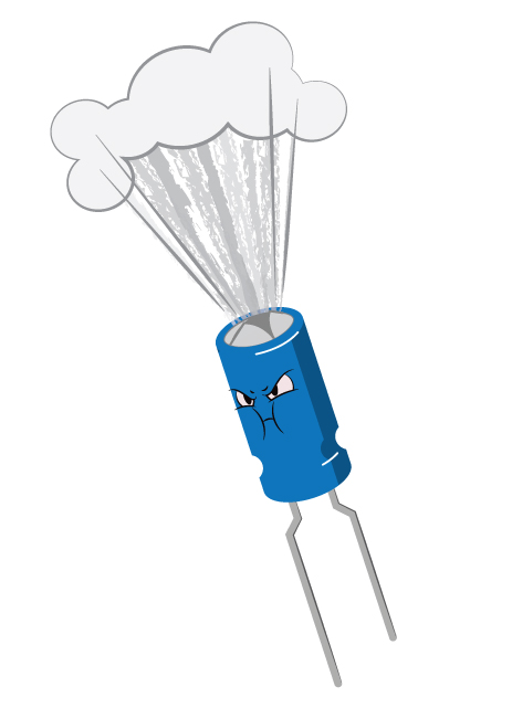
So, who's going to use Angry Capacitor as their profile picture? We used to have great fun plugging beer-can sized surplus electrolytics into 120V AC back in college. By that time the carcincgens were probably removed from the dielectric recipe. Hopefully...
Funny you should mention Tantalums and space hardware. We actually have an annoying problem with the occasional Tantalum capacitor developing shorts that heal themselves if in low impedance circuits (http://www.avxtantalum.com/pdf/SURGTANT.PDF). We have a power supply design that has a tantalum capacitor on each output that will very rarely see a dip in the output voltage. This isn't something you would normally see, but space electronics, especially rockets waiting for a launch, are heavily monitored.
Telephone grade electrolytic s last until the device is out dated - 20 years in some of my stuff.
I agree, but some chips (MCUs, GPUs, APUs, FPGAs/CPLDS), do recommend using tantalum and provide the appropriate requirements of what to use.
It is best to ALWAYS to look at the datasheets and see what is recommended for capacitors.
While designing a circuit with an MCU, i found out that it was possible to remove tantalums altogether by switching to Ceramics. The Input and Output Bypass caps of the LDO were changed to ceramics with low ESR. As @Kamiquasi said, to compensate for extremely low ESR, a series resistor of 1 ohm was added with the ceramic cap. See here: Texas Instruments Ceramic Capacitors Replace Tantalum Capacitors in LDOs
In my experience, they are also costly: you can easily get a strip of 200 or so 0.1uf ceramics for $3, a single tantalum might set you back $0.20.
I compare tantalums to ceramics as LiPoly to Lead Acid batteries. With performance gains you increase cost.
And chance for fire! :P
And tantalum is a conflict mineral: https://en.wikipedia.org/wiki/Conflict_minerals
I want a t-shirt with that exploding capacitor! :)
Good call. I'll suggest this, or just roll our own. I'd wear one...
Nice write-up! Although, I think it's the manganese dioxide cathode in the tantalum cap that is the truly evil part (polymer tantalums aren't as bad).
Also, not only does over voltage affect the breakdown, mechanical stress like heating during reflow can create weakness in the dielectric contributing to a breakdown. Proofing the capacitor is sometimes suggested (by applying voltage and limiting current) and can be done to "heal" the cap after reflow, but who wants to do that.
Great to hear from you!
Shawn - thanks for the capacitor overview. I agree that de-rating is an important concept that does not get enough attention and you've covered it well.
I would like to clarify a couple items:
"electrolytic capacitors cannot be used to couple AC signals"
This is not entirely accurate. I think what you are trying to say is that reverse polarity on a polarized electrolytic can make for a bad day. We (electrical engineers) use electrolytics all the time to couple one amplifier stage to another. The capacitor serves to couple or pass the AC signal while blocking the DC portion. If there is a DC bias present (so polarity is not reversed on the electrolytic), then electrolytics work well in this kind of an application.
There have also been quite a few comments already on tantalum capacitors, but I will add that they are preferred in high reliability applications (space, military, telecommunications) and places where the solid dielectric works better than the liquid/paste in an electrolytic and they tend to be smaller than ceramics (for a similar capacitance value). A 50% voltage de-rating is more than sufficient for electrolytic, tantalum, ceramic, and many other dielectrics as long as you do not stress them in other areas (e.g. ripple current in a power supply filter or thermal environment in the case of something mounting in an outdoor environment). Experimenters should not be discouraged from using solid dielectric capacitors like tantalum, niobium, and polymers in general. They should have a place in the designer's toolbox along side their larger, cheaper electrolytic cousins.
Thanks for the tips! You make a great point about AC signals - as long as you have a DC bias, you can use electrolytic capacitors with AC.
And I definitely agree with your assessment of tantalum capacitors. They have uses in specific applications - especially when you need a high capacitance in a small footprint. In fact, I just recently used one on one of my new designs because I needed 100uF in a small package, and ceramic capacitors just would not cut it. If you are absolutely positive about your ripple voltage, spikes, and that no one's going to reverse the battery connector, then you can do 30%-50% de-rating with tantalums. However, when we're dealing with hobbyists who might reverse the supply voltage (I've done it!) or use a noisy supply, then 3x might be safer. This is why I wasn't too happy with the choice of a 6.3V tantalum capacitor on the Arduino GSM shield :)
I don't think that people shouldn't learn how to design with tantalums or electrolytic capacitors, but I think 95% of the designs out there that are meant for hobbyists (e.g. SparkFun, Arduino, etc.) are perfectly fine with ceramic capacitors (maybe an electrolytic if you need it). You don't need to save the space in most cases and you're just asking for a fire if someone accidentally hooks up a tantalum incorrectly.
but but fire is so much fun... :'(
Yes, but we would not want a source of fun, electricity, adventure, and electronics burning to the ground would we?
The photo above makes me think; One of my electronics teachers told me that smoke makes all electronics work because when the smoke gets outs it doesn't work anymore! :)
We all know how tricky it is to get the magic blue smoke back in! https://www.sparkfun.com/products/retired/10622
I couldn't disagree more with most everything in this article.
The general rule of thumb is to derate by 30% (meaning use 70% of the rated voltage) unless you have a lot of ripple or transient currents. In circuits with high ripple or transients, you've got homework to do and shouldn't be following a rule of thumb without a full understanding. In that case, 2-3x derating may save you. If you're derating your bulk bypassing or filter caps by 2-3x it leaves you with an design that is unnecessarily expensive and large.
Despite the title, there is no discussion in the article of "why" to excessively derate capacitors. Electronic components are very precisely spec'd. Read and understand the datasheets. If the datasheet says "rated voltage X" it means that it will meet the specifications and it is ok to use at that voltage. Typically there will be a seperate "withstand voltage" that is significantly higher. Derating is done to ensure that there is sufficient margin in your design to ensure that you meet the component specs, not to ensure that the component performs.
Recommending avoiding tantalum capacitors is just silly. Tantalum capacitors have specific features that are sometimes very beneficial - although ceramics are getting to the point where they can fill in much of the time.
If board space and cost are your primary concerns, absolutely. As a few people have mentioned above, always read the datasheets. For most hobbyists and for prototyping, ensuring that the component performs is a major concern, in which case, I still recommend 2x-3x derating. However, if you are working on the next iPhone and board space is at a premium, then yes, tantalums have a definite use, just make sure to be careful about how you use them. Alternatively, if cost savings are a huge concern and you can save $0.001 on a capacitor by derating by only 30%, then by all means go for it, as this can translate to thousands of dollars in a huge production run.
For some general derating rules, check out the NAVSEA site. Most caps have a minimum recommended derating of 30-40% according to them.
I've seen people connecting two electrolytic capacitors in series but one with reverse polarity, this way you'll have a non-polarized electrolytic array. The only downside is that the capacitance is halved (because they are in series).
What is your stand with this method?
I can't say I have a stand on the method, as I personally have never seen it done. That being said, it seems like a legitimate way to make a non-polarized electrolytic capacitor.
Apparently, you can also buy non-polarized electrolytic capacitors, which look like two caps glued together.
Electrolytic caps that have been sitting for several years (not under power) need to be given a charge slowly so that they can "re-form" the capacitive layer. Antique radio guys use a variac (variable AC transformer) to start out old radios at a much lower voltage for this reason.
Also some caps will decrease in value if used too far below their rated voltage. (Caps that do this are usually, but not always, electrolytic.)
And then there was the rash of "counterfeit" caps that got onto computer motherboards a decade or so ago...
I love it whe you show actual failures and explain why the failure happens. Plus watchin the caps blow was a great way to start my day. Gosh, I love this stuff, now I just gotta figger out why...I was giggling like a kid when he popped the electrolytic.. Wheelchair Bob
[Watch Shawn Blow Up Capacitors] CLICK!
This is what I call edutainment. Informative and blowing stuff up is always fun.
This is a pretty good writeup. Just today I completed a white paper on why some tantalum caps on an old design were failing short and why the same caps on a newer design were ok. It all boiled down to surge voltages and our protection scheme on the older design being borderline for most cases. The cool thing is that I got to revisit surge voltage, ripple current, and TVS vs MOVs (for protection devices).
One thing I'll add, for most space applications we almost use tantalums exclusively (and of course ceramic). But for low ESR and density the tantalums still rule. We won't touch most electrolytic caps with a ten foot pole. Between the limited life at very high temperatures (if we must, we always select 105C rated or higher), and the very poor operation at very cold temperatures, our design review checklist for aerospace applications includes a check for absence of electrolytics. Now for my home projects that is a different story, the electrolytics are just much more cost effective (if you don't need the operation at extreme temps).
20 odd years ago one of the things I was doing was fixing entertainment strobe lights. It used a series of caps in a voltage multiplier ladder network to build up the voltage from mains ac, and even then they were a 10yr old design with a circuit board that was obviously hand laid out. After a certain time, especially if they were left on at maximum, about 15 flashes per second, the legs on the caps would break. They sat about 1/2" above the board on their legs, and I think the constant electrical surging setup slight vibrations that fatigued the legs and caused them to break.
I wonder if it was a heat stress due to the current or mechanical stress from the magnetic fields produced. Failures like this are always interesting. Science!
More likely flexing of the electrolyte with charge/discharge, coupled with heat stress. Wait a minute... 15 flashes per second?
What about derating temperature? For an MLCC i have an X5R with temp rating from -55C to 85C, I understand there is some tolerance 10~15% in capacitance when running at or near the 85C and over time some degradation. Anyone have any experience or expertise if temperatures can get up to 85C ~ 95C what might happen?
What happen when i put a 12V DC into ceramic 10uF/6.3V size 0603 10%???
You should try it and find out :) More than likely, the capacitor will fail, but not in an explosive way. The good news is that most ceramics will fail open.
What happen when i put a 12V DC into ceramic 10uF/6.3V - size 0603 - 10%???
Stumbled across this article and there's a few too many generalities and not enough background...
Derating ceramic capacitors is mostly done for the effect of capacitance loss as voltage increases, but the critical point is that different physical -sizes- have dramatically different rates of change. A 1206 SMD cap will lose rated capacitance much more slowly than a 0603 as the voltage rises (oddly enough, a 0603 cap probably won't have anywhere near the rated capacitance even at 50% the "rated" voltage, whereas a 1206 will probably be very close to the rated capacitance at 50% rated voltage)
In typical microcontroller circuits, where a single stable DC voltage is all that is ever expected, Tantalum capacitors make perfect sense and there's absolutely no reason to shy away from them. Tantalums also don't suffer significantly from voltage derating, so they can be relied upon to deliver a specific capacitance more or less right up to the rated voltage.
Tantalums are also a prerequisite in a lot of low-dropout voltage regulator applications, the ESR of ceramics is too low, and electrolytics are impractical.
Yes, Tantalums can go "pop" if connected in reverse and over-volted, but if you do things like that, the rest of the circuit is probably toast as well, so at least you know -right away- you did a bad thing! ;)
how to calculate capacitor voltage rating in circuit
Tantalum caps are excellent radiation detectors. They internally short. If they are current protected they recover. I don't use them for personal projects.
I think I may have to subject a few capacitors to increasingly higher voltages to fully visualise whats mentioned in this article :) mwhahaha
I think you'll find the result quite explosive. Be careful....flames do happen :)
Tantalums would make great model Rocket Engine igniters :)
Now this I need to try :D
I seem to remember reading that if you derated an electrolytic cap too much, it would not show the correct capacatance rating. IE: use a 100v cap at 10 volts and it would not "form" correctly and show a lower value than marked. Maybe that was true in "prehistoric" times and isn't a problem with today's parts.
I have a Tektronix TDS540 scope. When they were built they used 10V rated aluminum electrolytics on the 12V DC buses. Now after 15 years or so most of these scopes are dead. Some owners like me have replaced the 10V caps with higher voltage ones to keep the scopes running. So far I have replaced 66 caps on one PCB alone.
You couldn't find a bigger capacitor to blow up?? :D
The capacitance also decreases as the voltage goes up: http://www.maximintegrated.com/app-notes/index.mvp/id/5527
Why too much capacitance can destabilize an LDO: (hint: Phase-shift.) http://www.ti.com/lit/an/snva020b/snva020b.pdf
General info on choosing and using bypass capacitors: http://www.intersil.com/content/dam/Intersil/documents/an13/an1325.pdf
and there are other materials for capacitors such as mica and a couple of others..
Some other types -- paper-in-oil (usually used at higher voltages), teflon - usually used for higher voltages and/or RF, air dielectric - look inside an ordinary radio receiver, find the variable tuning cap, though some use polyethelene or polystyrene sheets between the plates. (making it, obviously, a polyethelene or polystyrene cap), vacuum dielectric - usually found in things that use high power RF, like high power transmitters, plasma generators and such.) Last but not least is the varicap -- not a capacitor like any of the above, but a diode that changes capacitance depending on the bias voltage across its junction, we'd not have things like the modern VCO (Voltage Controlled Oscillator) without this little beastie.
You should do one on the frequency response of capacitors.
Not a bad idea. Looking at a scope isn't as fun as exploding the caps though... :)
This summary does not explain derating ceramic capacitors, which lose their capacitance with a high DC bias.
See http://gasstationwithoutpumps.wordpress.com/2013/06/26/capacitance-depends-on-dc-bias-in-ceramic-capacitors/ and http://gasstationwithoutpumps.wordpress.com/2013/06/26/kemet-tech-reports-on-capacitors/
But... But... I have electrolytic capacitors that don't have a slit in it.
What happens if I overload it?
This happened to me and a projectile capacitor piece broke my skin.
Well, that's even more fun. Just don't stand over the top of it while it's overloading.
Yeah, the ones without the slit make an even louder pop. Not that I recommend trying this at home or anything :)
A while ago Agilent (they were still HP back then) ran an effort to increase quality by 10x. They reviewed failure reports from divisions all over the world and made a list of the most common failures. The number one failure was bad caps from lack of voltage under-rating. The new rule became overrate working voltage by 2x. This is the rule I follow when designing products.
About a month ago there was an issue with a Arduino GSM board referencing a tantalum cap. The blog entry was written by a guy working for Kemet and was an interesting read. http://www.baldengineer.com/blog/2013/09/13/ouch-the-arduino-gsm-shield-has-a-pretty-serious-design-flaw-with-its-capacitors/ http://hackaday.com/2013/09/24/safety-warning-arduino-gsm-shield-may-cause-fires/
The discussion of that exact incident is actually what sparked Shawn diving into this project if I remember correctly.
This is a good overview of the "big 3" capacitors and derating guidelines. Generally speaking, 2X the working voltage should suffice in a well designed circuit.
Tantalums can also explode with high dI/dt, even if the voltage rating is never approached. Battery power can be especially bad for that. Happened on a product I was working on, fortunately we had some prototypes go and redesigned it before it was released. Here's a paper from AVX with plenty of information... http://www.avxtantalum.com/pdf/SURGTANT.PDF
Another problem/consideration is cold. Most electrolytics won't go down to -40 degrees. It might not usually be a problem, until you leave your device in the car overnight in MN, ND or somewhere else during an arctic clipper. Also note the high altitude balloon photography is usually in an insulated container.
I haven't yet looked at how the various types react across the temp range, but it would be interesting.
That might be a fun experiment to try. MikeGrusin (above) made a reply about how they can't use electrolytics for use in space because of humidity/temperature concerns.
WhAt!? There is humidity in SpAcE!?
Or lack thereof :)
Aren't most tantalums made with a substance that when it blows, that turns into a gas and it isn't that fun to inhale(more so than the others) or am I thinking of some other type of capacitor?
They used to fill big industrial capacitors and transformers with PCB (not Printed Circuit Board), which is pretty nasty stuff.
Yes, I failed a Tant with my mouth open while standing close, and I could taste evil for four days! Nasty stuff. Those tiny things can emit a surprisingly large amount of evil. Another evil feature: the stripe on a Tantalum capacitor is the (+) electrode, not the (-), as on aluminum-electroytic capacitors. The aforementioned failure event taught me this valuable lesson. Slap an RTFM on that one.
I've had MULTIPLE tantalum capacitors explode in a production power supply at work. They work great most of the time, but when they explode it's exciting. This was a small 6.8 uF 35 volt tantalum cap. We used safety glasses on that power supply. (We finally got the engineer to change the design.)
This is very helpful; I did not previously truly understand the differences between types of capacitors.
Glad to hear you liked it!