
When designing a board, power is always a concern. Not matter if the power supply is batteries or a wall wart, you have to consider how the user is going to attach the power supply. Given the opportunity, we have to assume that power will be hooked up wrong. This brings up the discussion of 'reverse power protection'.
How would you design a circuit to withstand having the power applied backwards?
If you've ever plugged in a chip backwards, a wallwart backwards, or shorted VCC to GND, you know what we're talking about. And if you haven't hooked something up backwards, you're not human.

Chris Anderson recently brought up this discussion with me over the ArduPilot. This small board is a good example of the different options available. You can see the small BAS16 diode highlighted in the above Eagle PCB layout. This small diode is designed into the product to protect against reverse polarization. If someone hooks power up backwards, the diode fails to forward bias and the board simply doesn't turn on, protecting it from damage.
1) Inline protection diode: The problem is the forward voltage drop of the diode.
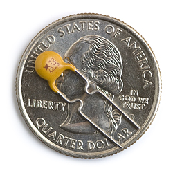
D1 is an 'inline protection diode'
Cheap diodes have a theoretical 0.7V drop. So if you hook 5V up to the board, you'll get 5-0.7=4.3V delivered to the board. In practice, the forward drop of the diode is actually a bit lower (0.5V) and there are specialty diodes available that have even lower forward drop (germanium?). This all works great if your incoming power is 2-3 volts higher than your output, but if you're running a 5V board from a 5V source, the diode will drop the voltage to your system down significantly.
2) No protection: This is my favorite because it's so dangerous!
No protection diode!
Do we really care? Can the electronics survive if we put the batteries in backwards? If you're designing your own board, running without any protection can very questionable. Many current electronics can survive reverse power without any ill effects, but if you're playing with any part worth more than $5, I'd get something on the board to protect my parts. The beginning embedded electronics tutorial #1 will show you how to create a good bread-board power supply. At the very least, I recommend large, clear labels on the power pins:

Checkout the Eagle DFM tutorial for more information about labeling your board.
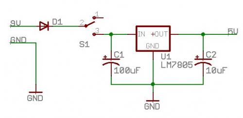
3) Voltage Regulator: The nice thing about many voltage regulators is that they have short circuit and reverse polarization protection built in!

LDO Voltage regulator with two 10uF tantalum capacitors
We love the Micrel part (MIC5207). You can do some really mean things to this SOT-23 v-reg (shown above) and it will survive and protect the electronics behind the regulator section of the power supply. These regulators are better than a diode because the forward drop of the MIC5207 is ~100mV under load - much less drop than the diode option. The problem is that a voltage regulator can handle less current (180mA max), is physically larger (with required caps), and is more expensive ($0.50 vs $0.07) than a similar sized diode.
Note: Reversing the voltage on electrolytic or tantalum caps is a bad thing. A 16V rated tantalum may "pop" (explode with great force) if you apply 10V the wrong way. Electrolytic caps won't explode as violently, but may expand or puff out a bit.
4) Polarized battery connector: Using a polarized connector like the SMD JST 2-pin connector instead of a bare 0.1" spaced connector.
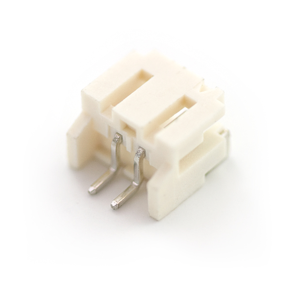
Polarized power connectors
This connector makes it more difficult for people to willy-nilly attach a battery pack or power supply. This can initially be frustrating, but it forces the person to terminate their battery or power supply correctly. Once terminated, the user can quickly plug in the battery and not have to think about it. This works but may not provide infallible protection (the user may terminate a 12V wall wart to an intended 3.7V connector). We use this option all the time for our LiPo powered projects.
5) Resettable Fuse PTC (Positive temperature coefficient) : Using a resettable fuse is $0.30, slightly more space than the diode and is cheaper than a full voltage regulator solution.
The PTC will cut off power if there is a current draw of more than 250mA. Removing the problem or short will allow the PTC to cool off and current will flow again. More info in this tutorial. Think about this carefully as the extra peripherals may add up to 250mA causing the PTC to trip incorrectly. We love using PTCs to help protect the electronics from short-circuit failures, however many voltage regulators already have this feature built-in.
Any project will require careful thought and planning when creating a reliable power supply that can withstand regular abuse. What other tricks have you found that help protect your designs?


Using this method, I've never toasted a thing:
http://img176.imageshack.us/img176/8501/protectionrj3.png
F1 is a PTC polyfuse. Generally rated 2x above my max planified current.
D1 is a Zener, with breakdown voltage a bit below the absolute maximum rating of the weakest part
D2 is a Schotky with the lowest possible VForward. I'm usually using Toshiba CMS01 with 0.3V forward.
Now, the explanation:
Let's say you plug the thing straight: the PTC won't trigger and do not dissipate much heat.
If the circuit short, or a big undesired current draw happens: F1 will climb it's resistance value and contain the problem.
If someone plugs the thing backward: D2 will let the current flow, and F1 will activate to lower the max current flowing trough the loop. Since D2 has a VF of 0.3V, the circuitry will have to resist to -0.3V, and most of today's chip does.
Then, if overvoltage happens, D1 will clamp the voltage to an acceptable value, and if it stays that way for too long, F1 will activate too.
Complete protection that won't cost you too much of your precious power input.
I was just going to post the same circuit. This is how I design all my projects. No destroyed caps, no reverse polarity, and no over-current conditions. It is also a good idea to put a reverse diode on any voltage input measurement circuitry that to prevent damage to sensitive cmos components like analog switches from a temporary negative supply while the polymer fuse is bysy heating up to trip point.
-tve
Nice solution! It adds a few parts but they are minimal and relatively cheap. Thanks!
Re. the inline diode technique. Since you're using an LM7805, have you tried placing the protection diode (or an npn or nfet) in series with the LM7805 GND pin with a pull-up resistor to the IN pin?
When connected properly the diode would be on, grounding the LM7805 and outputting Vreg+Vdiode. When reverse-connected the diode would be off and the pull-up resistor would float LM7805 GND to VIN, keeping the circuit off.
Haven't tried it myself, but looking through some of the LM7805 datasheets they show 'adjustable output regulator' circuits that raise LM7805 GND in a similar manner.
Philip: _... I have even seen geraniums with less than .1v _
Funny, I've never thought of using flowers in a power supply.
Thanks I needed a laugh today, Sorry for the misspelled words;
Rum + keyboard = BAD SPELLING !
germanium
At present I use the Diode version, so far the power is always powering a 7805 of some sort, so the v drop is no big deal.
However, most of my designs interface to another device on the RS-232. My concern then is the ground side as my adapter shares ground with the other device. If V+ is applied to the ground on the interface, V+ will flow into the device it is connected to. I can only hope that the other device has some sort of protection. I can't put the diode on the ground side because again, that lowers all output levels by the v-drop of the diode. I will look into what clothbot and Jay2 posted.
The polarized connector Idea works in theory, unless you are providing the power supply with the matting connector it is a poor design for sole polarization protection. Even if you are providing a "pig-tail" with the proper mating connector there is no guarantee that the hot wire will be connected to Positive. Most electronics use Red/Black as Hot and ground respectively, others use Black/White, black being Positive. Far to often I have seen people letting the smoke out of the wires regardless of a polarized connector.
Lastly, a question for Sparkfun. If the PTC is a $0.30 solution, why then do you sell them for $1.25?
I usually use a reed relay and two diodes. It seems like this design is very popular in Europe. This design ensures that there will be no voltage drop.
http://img297.imageshack.us/my.php?image=relayrf2.png
D8 and D9 are standard diodes with 0.7V drop.
When you plug it in normally, current will travel through D8 into the solenoid. The reed relay will close and current will flow through into your circuit board.
If someone plugs it backwards, D9 will allow current to flow through to D8 and the reed relay won't get activated.
I usually use a reed relay and two diodes. It seems like this design is very popular in Europe. This design ensures that there will be no voltage drop.
http://img297.imageshack.us/img297/3342/relayrf2.th.png
D8 and D9 are standard diodes with 0.7V drop.
When you plug it in normally, current will travel through D8 into the solenoid. The reed relay will close and current will flow through into your circuit board.
If someone plugs it backwards, D9 will allow current to flow through to D8 and the reed relay won't get activated.
Philip: HEY,
Use a bridge rectifier, input DC on the ~AC - ~AC,
and you get the correct polarity on the - + DC side every time. The DC output of the bridge still has to be regulated, done this for years when connecting to a power supply of unknown polarity.
Note that doubles the rectifier voltage drop since you go through 2. Also, your power supply GND will be a voltage drop above the GND of the power source. Neither are killers but you should be aware of them.
The in-line MOSFET is the best way to avoid a drop.
Yes philba,
You are right, I was not implying there was no need for regulation, but for the average hobbyist, mosfets are above and beyond. Now don't get me wrong, mosfets are very cool and everyone should learn about them. My post merely is a simple and quick solution for circuit protection.
"When designing a board, power is always a concern." I guess so, given that it's hard to run a board without it. lol
Right. Good point. :) I guess I should have said 'power input is always a concern'.
As someone who worked as a radio technician, I agree with DeanMurray's approach. When you had a $2,000 mobile radio (in 1980's money) you didn't want it blown up by somebody not being able to tell the difference between the red and black wires. So all radios had a big diode reverse biased near the connector. If the power was reversed, the diode would short and blow the fuse. I guess it was job security, but I sure replaced a lot of those diodes.
If your radio and power supply are grounded reverse connecting will usually place a dead short across the power supply.
I've used bridge rectifiers, but with either a diode solution or a bridge rectifier, you need to be aware of the current requirements. A rectifier needs to dissipate 1.2V * Current in Watts. At 2A, your generating 2.4W of heat, which might burn out the rectifier or cause other problems.
Reza
HEY,
Use a bridge rectifier, input DC on the ~AC - ~AC,
and you get the correct polarity on the - + DC side every time. The DC output of the bridge still has to be regulated, done this for years when connecting to a power supply of unknown polarity.
Bridge rectifiers are built of diodes, so you still have the voltage drop. It also won't protect against overvoltage/overcurrent conditions.
Yes graealex,
You are right, the bridge will not protect against over voltage, and the voltage drop is minuscule, .8 v to 1.4 v. If that is too much for you assemble a bridge from Shockley diodes, .1 v to .3 v drop. BUT.... if you refer back to your "school books" and look at how the diodes of a bridge are assembled, you will see that no matter the polarity of the input voltage; the diodes will steer the current to its appropriate polarities.
If you have any questions, refer back to AC/DC theory 101.
Schotky Diodes tend to have 0.3V of forward drop minimum, and 0.6V drop is far from "minuscule" in a battery powered item. The drop inside a single Mosfet or a single untriggered PTC is a lot less.
Oh yea,
One more thing, the question was;
"How would you design a circuit to withstand having the power applied backwards?"
My favorite method is to use a 3 prong connector with the center pin being power and the two outer one's being ground. This way no matter what way they plug in the connector, as long as they are on all 3 pins, power gets applied correctly.
lots of broken image links in this article. (13 August 2017) Maybe someone at Sparkfun will notice this comment :)?
Just joined in because of the need to see the circuit mentioned here, "http://img176.imageshack.us/img176/8501/protectionrj3.png". Has this link been corrected yet? I'm not able to see the circuit as yet,Thanks.
Yeah, this is an old blog post. Our IT department might have changed some things with our server causing the links to break. They should be fixed now. =) I also did a little formatting. ^_^
Thanks for letting us know, looks like an older tutorial and an update probably broke something. I'll see about getting that fixed.
One thing I've noticed about the PolySwitch resettable fuses is the tripping time.
This is generally very good for fuses designed to trip at say 0.4A - they can trip in 0.02seconds! However, I was trying to implement some sort of reverse polarity protection in a motor controller circuit whereby the motors together could easily draw 3Amps from the 24V supply while running. The fuse therefore had to be rated above this to allow the 3Amps to pass and when you get into this territory you're talking about 5seconds for a Resettable fuse to trip. This would be useless for reverse polarity protection!
I always used the regular 2.1 barrel plugs and connectors for my projects, but I am thinking of switching to the polarized battery connector. Checking the Sparkfun's products is a little confusing though.
Some products (like 9V snap connector PRT-00091) use Molex, some products (like the LiPo Batteries or the barrel adapter TOL-08734) use JST and some products (like 5V DC to DC Step Up PRT-08248 and PRT-08249) do not specify what is used. Is there a standard?
My understanding is, that Molex is 0.1" (2.52mm) and JST is 2mm. I guess 0.5 mm is not much, but the plugs look different.
I was thinking of using the JST connector. The two connectors (PRT-08612 and RT-08613) are both compact surface mount connector. I have never done any surface mount soldering - can I solder these with my regular solder iron (carefully from the side)? Is there a JST through-hole connector?
Philip:
The voltage drop across a diode depends on how much current is being passed through it. If you draw a fraction of a milliamp through a 1N4001, you won't see anything near 600 millivolts across the diode. The 700 millivolts is just a rule of thumb and is close to what you can expect if the device is being used near its maximum current limit.
In typical circuits the drop is closer to 600 millivolts for silicon diodes.
testing with 1N4001 1 amp diode
Current Draw = 0.94 amps Vd = 0.8v
Current Draw = 0.04 amps Vd = ~ 0.1v
Meter Diode test = Vd = 0.5v
Just to show the Real life difference.
This is FYI for all, I have been a bench repair tech for several years now, and have rarely seen a common 1n4001 with .7 v drop across the junction. Typically it is anywhere from .3 to .6. The .7 v drop is simply a generic basis taught in school. I have even seen geraniums with less than .1v . For a little background, I have tested and repaired Industrial monitors, AC / DC motor drives, Microwave frequency generators and amplifiers, even cell phone linear amplifiers 900Mhz - 1100 Mhz, etc.... Not trying to be an A$$, just sharing what I have learned through the years, Thank all of you for the insight and interesting ideas.
All the things mentioned help, but as a first line of defense, I like to use:
AMP MTA .100" Series IDC Connectors (Polarized)
AMP MTA .100" IDC Headers (Polarized)
$10 Insertion Tool
It saves a lot of head scratching and smoke. When you are sober, you can only plug it in the right way! I bought 100 of the 4 pin and use them on everything. You can gang two or 3 of them together with superglue if you need more pins. Use the .001 version for most things. Or the .156 version if you need more amperage.
If you cant afford the voltage drop from the diode and don't need regulation you can put the ptc or fuse inline and then a power diode (depending on the supplies short circuit current) in parallel. correct polarity is ok, reverse polarity causes short through the diode which causes the fuse to blow. Your circuit will see at most .7v revere polarity for a very short time.
I generally prefer the polarized connector approach for minimum cost. But using a MOSFET like the following link is best when the device is powered by replaceable batteries.(unless the battery contacts are mechanically polarized.) If you can't afford the diode drop of option one, the fet is a great solution.
Power supplies using a Li coin cell or just one or two AAA cells will really benefit from this trick. I am partial to the IRLML2502 in this circuit because of it's low cost, Rds, Vgs, and high drain current limit.
http://electronicdesign.com/Articles/Print.cfm?ArticleID=9945
http://www.geofex.com/article_folders/mosswitch/mosswitch.htm
http://www.irf.com/technical-info/designtp/dt94-8.pdf
Why not have a switch in your power line that is turned on by correct polarity and otherwise off? This can be done with a single N- or P-MOS (and possibly a gate resistor if you like). Expansion of this idea can turn into a 4 FET system which will provide correct polarity to the circuitry regardless of hookup polarity and still provides low (dependent upon selected FETs) losses.
http://www.eng-tips.com/viewthread.cfm?qid=149960&page=8