It's Friday, the building is close to being empty, and beer and thermodynamics are on my mind. Wanna know why?


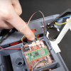
This is a fun project involving a thermoelectric fermentation chiller for beer wort using SparkFun parts and BatchPCB. Thermodynamics, electronics, and beer, what a great combination. Awesome work Adam!

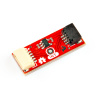
Ardumoto. Take a guess. This is a motor shield for an Arduino USB or Arduino Pro that will drive two DC motors, 2 amps per channel.

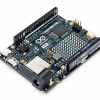
The ARMmite Pro is a ARM based board with a Arduino Pro footprint. Packs a much bigger punch than the AVR Arduinos. 32 bits of processing power running at 60MHz turns this board into a low cost single board computer.

A new Olimex development board. The AT90USB162 is the easiest way to add USB functionality to your next project. Atmel provides free open source HID (mouse, keyboard) and CDC (USB-to-RS232)
code.

This is one powerful motor control board. The Dual Serial Motor Controller allows for variable speed and direction control of two large brushed DC motors using a simple serial interface. 13A continuous and 30A peak output per channel!

This is one powerful motor control board. The Dual Serial Motor Controller allows for variable speed and direction control of two large brushed DC motors using a simple serial interface. 13A continuous and 30A peak output per channel!
Here is a cable we designed for the ButtonPad Controller Board, but can be used with any4-pin JST connector.

The new ADXRS 6 series gyros are now available. Comes in three flavors: 50, 150, and 300 degrees per second.

The LilyPad Main Board now come with an ATMega328. It's like the ATmega168, but with double the flash space (32K), double the SRAM (2K), and double the EEPROM (1K).


How about about a bit of experimental method rather than farting around in dorky implementation.
The time you spend with a physics textbook will save you money and time, then target your implementation to this.
If it happends to be a peltier, hip-hip hooray, but I am not yet convinced. Death, taxes, nurses and the second law of thermodynamics.
Apologies for coming on too strong, or offending delicate bloggers on this post. Rise to the challenge of controlling lower finesse beasts like heater elements and cooler pumps rather than hoping a p-n junction will sell. On the other hand if this is a marketing pitch to sell peltiers and control electronics, just let everyone know.
Here are some quotes that come to mind:
"When you are a hammer, everything is a nail"
"In life, few things are certain: death, taxes, nurses and the second law"
I look forward to being kicked off the posting.
what a lame project. If the guy new anything about wine or beer making, or thermodynamics, he wouldn't use a peltier.
a pump with ethelyne glycol or a heat pad would make a much better actuator given his thermal mass.
Please read the blog first:
"Overall for a system of this size or larger, a typical compression refrigeration system may be more efficient - but that wasn't the point of the project."
what is the point of the project then? If it is not to regulate temperature of a home brew then maybe I am missing something.
I am not aware of anyone who brews beer in less than a 23-L batch (5 gallons or thereabouts). You can brew smaller starter brews for experimentation but that is not what this blogger was proffering. The minimum would be a 5-10L batch unless you wanted to 'cuddle' the wort as a starter and maybe a peltier would be useful here. However I didn't see your ad say "home brew yeast starter with a peltier" and your photo was of a 23-L carboy.
Skip, not sure you looked closely enough. The heat flow calculations are all there, you just need to plug the numbers in. The first implementation is a prototype using small vessels, just to get the idea of how the control electronics would work.
It is very doable to cool 5 gallon fermentation vessels this way. It becomes difficult if you want them extremely cold. In the same manner, there are also many thermoelectric refrigerators for wine storage out there currently.
Also, this project is for pure enjoyment of the hobby, and anytime you have the chance to combine two hobbies, more power to you. As this is a hobby, there is no need to follow strict rules of implementation. I apologize if you were deceived.
Oops, here is a slight correction to my last comment...
The roll your own circuit would have the PNP transistor set to pull the gate high when its base is pulled low, the first NPN transistor would be set pull the gate low when its base is pulled high, and the third NPN transistor would be used as an inverter to invert the signal to the PNP base, thus insuring that the gate would be alternately pulled either high or low but never both high and low at the same time.
Re: Beerware
I would suggest changing the drive signal to the FET so that the FET is either completely off or completely on. When the FET is driven in this fashion the power it dissipates (wastes) to its heat sink is minimized. This is more important as you scale the design up to larger cooling loads.
The FET drive can be PWM with the amount of cooling provided being set by the duty cycle of the PWM signal.
One note, there is capacitance in the gate of the FET that must be considered in the PWM drive signal. Therefore if the FET is being driven at a high frequency, a low impedance circuit must be used to turn the FET on and off rapidly to minimize the time that the FET is in the transition region between being fully on and fully off.
Happy brewing.
noworries - can you give an example of the low impedance circuit required to create the rapid on/off to drive the FET?
You could roll your own using two 2N3904 and one 2N3906 transistors and three resistors, or use a buffer IC like a LM6125 that is designed for driving capacitive loads at high frequencies.
I would send you a schematic, but I don't know how to attach a document here.
If you give me an email address I could send you a schematic.
The roll your own circuit would have the PNP transistor set to pull the gate high when its base is pulled low, the first NPN transistor would be set pull the gate low when its base is pulled high, and the third NPN transistor would be used as an inverter to invert the signal to the PNP gate, thus insuring that the gate would be alternately pulled either high or low but never both high and low at the same time.
Hope this helps...
Calif beat me to it. I completely agree with him. I think a lot of people would love to see a gyro and accelerometer guide similar to your recent GPS guide. It would also be convenient if you mentioned your IMU devices and what they use.
My next project will require something like this and I'm not sure which of your products fits my needs best. The datasheets help some, but an article from people with real hands on experience using many of these products would be invaluable.
Re: "The LilyPad Main Board now come(s) with an ATMega328. It's like the ATmega168, but with double the flash space and 32K of program space."
The flash space is the program space. The 328 also doubles the RAM (to 2K) and the EEPROM (to 1K).
Cheers,
--Dave
You definitely need to aggregate comments for items with multiple ranges & breakout board options like the gyros.