Engineering Roundtable - Nick and his DIY Camera
Check out today's edition of "Engineering Roundtable."

Today we have another edition of "Engineering Roundtable!" First, let's talk a little bit about today's host - Nick Poole. Nick, SparkFun's catalog curator, describes himself as an "execution guy." He excels in design and fabrication, finding novel solutions for code, board layout and interface problems. With an interest in wearable electronics and computing, Nick focuses not so much on theory, but on practical empirical electronics knowledge that gets him, and SparkFun, from point A to B. Nick's background in electronics is nothing if not diverse. The son of a mechanical engineer, Nick's childhood toys weren't matchbox cars and footballs, but howevermany-in-one electronic kits and a VTech children's laptop. Nick spent his youth building robots and writing simple computer games in BASIC. At the end of 8th grade, his middle school principal called him into her office - not to give him a detention, but to ask Nick to give her a briefing on computer security. For Nick, electronics have always been a labor of love.
Today, Nick takes you through his build of "The Big Ugly Camera." Check it out:
Nick took a few photos to give the camera a trial run. The photo on the left is the "source" photo and the photo on the right is using Nick's camera.
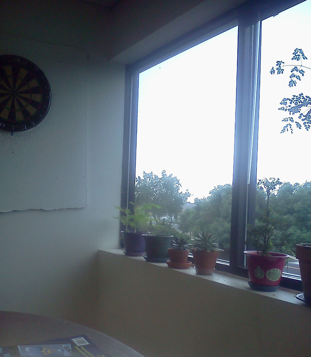
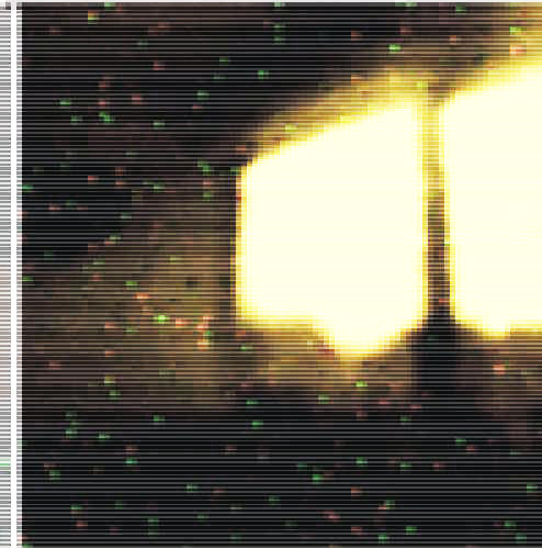
Yeah, maybe the photo is not too clear - but the proof of concept is definitely there. Check out the video above and feel free to leave any questions in the comments section below.


Years ago a coworker and I were fooling around with his Apple II computer. We interfaced an old 4k x 1 22pin (400mil wide) dram to the machine using a GP IO card. What we had done was to carefully peel off the metal lid from the dram chip (it was a ceramic case) and glue a microscope slide cover in place of the lid. We tried several different brands of drams and found one that had TWO groups of storage cells, both of which were 2x1 rectangles in size. You can find dram chips with a single large block of cells, and also some with 4 groups of square cell blocks. Anyway the idea was that the capacitor storage cells in a dram are sensitive to light which will cause them to discharge faster. So what we did was to write all ones (or zeros) to the cells and then read them back after a short interval. I found a short focus lens out of a cheap camera's viewfinder that I had taken apart. We mounted the lens and the IC in a jig so we could focus the lens onto the dram storage area. The software would charge the cells, wait, and read back. It then plotted the resulting "image" onto the Apple's graphic screen. By re-reading the cells we hoped to get some gray scale, since the longer we waited before a cell discharged the less bright was the light on it. Our test subject was the wattage label on the top of a 60 watt light bulb. We were really excited when we saw the "60" on the Apple II screen!
As soon as you said DRAM, I knew where this was going. That is an awesome hack, I love it!
Oh, this reminds me so much of Steve Ciarcia's digital imaging games in Byte, back in the mid-80's. He wasn't getting color, and his images were elongated by the geometry of the DRAM he was using, but that was when I knew that film cameras were doomed, at least for casual point-and-shoot usage.
Flippen Awezome!!! :D
I want to have an office like that someday. Jumper wires hanging down. 3 1602 displays chilling off of a shelf. A hot air rework station along with multiple multimeters. I would be in heaven. "Oh hey whatcha up to?" "Oh just inventing!" "GOOD! thats what we pay you for"
Yeah, I'm gunning for the position of "Professional Mad Scientist" but I'd settle for "Executive Director of Cartoon Villainy"
Why did you have the servo return to the x origin after every line? Would it be possible to use the x return to scan the next line?
Absolutely, and it would've made the process somewhat faster, I would've also avoided the "missing pixels" problem. The short answer is: I just didn't. Just getting this project to spit out a photo in the allotted time was a bit of a challenge.
If you were scanning back and forth, though, it would be a pretty quick change in the code. Whereas now it basically does this:
It could do something like this:
You really have the awesomest job evar, you know that right?
I'm thankful everyday, man
That was super cool! Thanks for "making" me waste 15min at work!
What I'd really like to do with this project, going forward, is replace the color light sensor with our MLX90614 IR Thermometer. If I get any interesting results, I'll try to mention it in my next video!
Make sure to get either the BCI or DCI version of that sensor. They are the smallest FOV versions of the sensor. They both take different filter settings to get to work properly. I have the BCI version of the sensor and tried to use the DCI settings from Max's website (www.cheap-thermocam.tk) and it ended up not working out. I put it back to the stock settings and it seems fine. Just be sure to read out the values before you change anything.
Thanks for the heads up!
It would be interesting to see the sensor responses and the image quality with the other two sensors https://www.sparkfun.com/products/11195 the cylindrical one and the Avago ADJD sensor.
It is possible to sweep the servos with a resolution of 180/(1400 to 1800) Us. You could either write the custom PWM code in WinAvr or even by modifying the Arduino servo lib to taken in the angle argument to be the pulsewidth rather than the angle. Instead of using a rack and pinion gear arrangment you could use a pulley and timing belt with smaller teeth using the same servos and you would get a resolution equal to that of the steppers with the same servos. It is a really nice project. I like you idea of taking the basic fundamental and working on it. At a fundamental level you are creating some thing new. I was thinking if the the frequency of the operation of the color sensor is high say at 1000 Hz then could it be possible to use a scanning/rotating mirror arrangement to read light back.I know the reverse is possible using a laser. If you keep a rotating mirror before a laser then you get a line instead of a dot. And if you have second mirror which rotates perpendicularly to the first and also does a second reflection of the laser you can get an entire X-Y image out of this laser projector arrangement. I was thinking what if one can read light back with such an arrangement.I wonder if additional focusing optics would be required? But if this works then one can reduce the scan time by a huge factor and may be even read successive frames as in a video.
Trying to capture color doesn't look worth it. Would be neat to see a pinhole with a bare photodiode on an XY table. That's a novel capability rather than a clone of a DSLR.
Yeah, it was sub-optimal, that's for sure, lol. A pinhole with a photodiode was my original idea (I explained that in part of the video that was cut out)
You can't fairly call this a clone of a DSLR, though, It's much more like a point and shoot. There's no "reflex," thus no "SLR"
Hehe. I built a similar camera using your Sharp distance sensor. I mounted it right on the servo head eliminating the need for the complex gantry mechanism.
www.sparkfun.com/products/8958?
Check the comment section, it has illustrations. I later made a switchable head accommodating various sensors to achieve multiple spectrum analysis.
https://www.sparkfun.com/products/10976 Seems like these slide pots would have been perfect for controlling the x-y position of your sensor. Any reason you didn't use them?
Awesome project btw, this is the kind of thing that keeps me coming back to this site!
I used those to build an XY rig for the MechanoPong project, I wasn't impressed with the amount of power they had. (They aren't actually meant to carry a load, after all)
You can check out the MechanoPong video here
Why on heavens earth did you NOT use red Sparkfun Boxes? They are everywhere including being used as set decoration. I kind of thought it was your mascot and you have Meet and Greets with it like at Disney World. :-)
If you swap the colour light sensor for a thermopile, this would be great to make a cheap(ish) thermal camera for looking at the heat distribution of PCBs. I really like the leap from your first prototype's sweeping motion to the XY motion of the final B.U.C.
Help me out Nick, you would be the perfect person to answer this, If I put the here-mentioned colour sensor face up in the bottom of a white box, then shine one of the lower power green lasers you stock into the white box from a distance, could the sensor pick up the laser as hitting the box?
I think that depends largely on the ambient light conditions. I'm having a hard time envisioning what you're doing but as long as the sensor was adequately 'washed' in reflected laser light, it should definitely register a spike in the green channel. You may need to write something so it can calibrate itself to the ambient green level and adjust the trigger threshold. It shouldn't be too difficult to pull of though.
By the way, one way you could automatically white-balance the image after the scan is done would go like this:
This reminds me of the high-end Dainippon Screen drum scanner at the prepress shop I worked with. That was also a single-pixel device, but the originals were mounted on a high-speed glass drum; the optical system was a halogen bulb feeding the focal point through (I think) 8 fibre optic lines to a set of photomultiplier tubes with a sensitivity of INDIVIDUAL PHOTONS. In transmission mode (for transparent originals) it could differentiate 5.00D from 5.01D, and its resolution limit was something like 5,000 pixels per inch. Fabulous!
This sort of reminds me of old mechanical TV.