- Home
- Product Categories
- Color
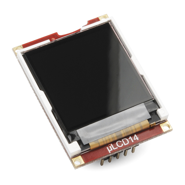
- Serial Miniature LCD Module - 1.44" (uLCD-144-G2 GFX)

The µLCD-144-G2(GFX) is a compact and cost effective display module using the latest state of the art LCD (TFT) technology with an embedded GOLDELOX-GFX2 graphics processor that delivers ‘stand-alone’ functionality to any project. Powerful graphics, text, image, animation and countless more features are built inside the GOLDELOX-GFX2 chip.
The module is designed to work out of the box and you are now ready to write your code in 4DGL (a high level 4D Graphics Language) using the 4DGL-Workshop3 IDE (editor, compiler, linker and downloader). This will save weeks even months of development time on your next embedded graphics project.
4DGL is a graphics oriented language allowing the developer to write applications in a high level language, syntax similar to popular languages such as BASIC, C and Pascal. The module offers modest but comprehensive I/O features that can interface to serial, analogue, digital, buttons, joystick, sound generation and Dallas 1-wire devices. In short, the µLCD-144-G2(GFX) offers one of the most flexible embedded graphics solutions available.
Note: This module is shipped with the "GFX" firmware. Either firmware can be loaded onto the device, however. For more information on reloading the firmware, see the 4D Systems product page below. Also, It's been brought to our attention that trying to program the 4D screens using an FTDI breakout can damage the driver. You'll need to use the FT232RQ USB to Serial which you can find in the related items below.
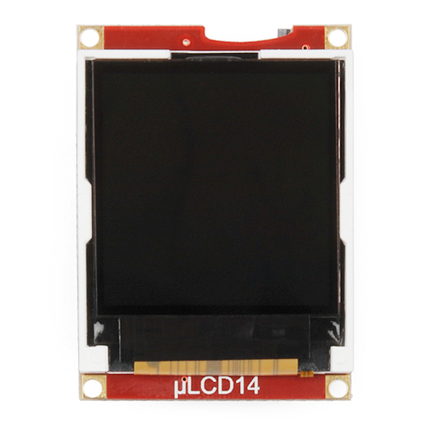
- 128xRGBx128 resolution, 65K true to life colors, LCD-TFT screen
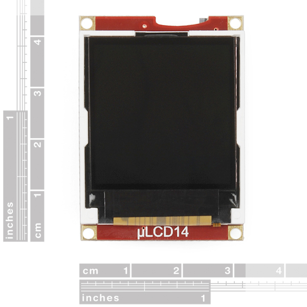
- 1.44” diagonal size, 43 x 31 x 6.4mm. Active Area: 25.5mm x 26.5mm
- LED back lighting with greater than 150° viewing angle
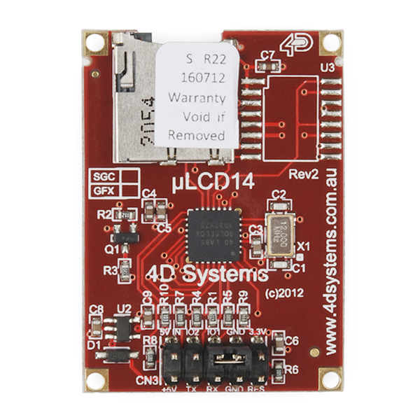
- Easy 10 pin interface to any external device:
• 3.3Vout, IO2, GND, IO1, RESET, GND, RX, TX, +5V, 5V OUT - Powered by the 4D-Labs GOLDELOX-GFX2 graphics processor highly optimized for 4DGL, the high level 4D Graphics Language.
- 2 x GPIO ports supports:
• Digital I/O
• A/D converter with 8/10 bit resolution
• Complex sound generation
• Dedicated RTTTL tune engine
• Multi-Switch Joystick
• Dallas 1-Wire - 10K bytes of flash memory for user code storage and 510 bytes of RAM for user variables (255 x 16bit vars)
- Serial TTL interface with auto-baud feature (300 to 600K baud)
- On-board micro-SD memory card adaptor for storing of icons, images, animations, etc. Supports 64MB to 2GGB micro-SD as well as micro-SDHC memory cards starting from 4GB and above
- Comprehensive set of built in high level 4DGL graphics functions and algorithms that can draw lines, circles, text, and much more
- Display full colour images, animations, icons and video clips
- Supports all available Windows fonts and characters (imported as external fonts)
- 4.0V to 5.5V range operation (single supply)
Serial Miniature LCD Module - 1.44" (uLCD-144-G2 GFX) Product Help and Resources
Everything You Should Know About HyperDisplay
February 20, 2019
This is a tutorial to go in-depth about the SparkFun HyperDisplay Arduino Library.
Core Skill: Programming
If a board needs code or communicates somehow, you're going to need to know how to program or interface with it. The programming skill is all about communication and code.
Skill Level: Rookie - You will need a better fundamental understand of what code is, and how it works. You will be using beginner-level software and development tools like Arduino. You will be dealing directly with code, but numerous examples and libraries are available. Sensors or shields will communicate with serial or TTL.
See all skill levels
Core Skill: Electrical Prototyping
If it requires power, you need to know how much, what all the pins do, and how to hook it up. You may need to reference datasheets, schematics, and know the ins and outs of electronics.
Skill Level: Competent - You will be required to reference a datasheet or schematic to know how to use a component. Your knowledge of a datasheet will only require basic features like power requirements, pinouts, or communications type. Also, you may need a power supply that?s greater than 12V or more than 1A worth of current.
See all skill levels
Comments
Looking for answers to technical questions?
We welcome your comments and suggestions below. However, if you are looking for solutions to technical questions please see our Technical Assistance page.
Customer Reviews
No reviews yet.
This product page is really out of date, go to the 4D Website for accurate information and go to the uLCD-144-G2 Product Page. http://www.4dsystems.com.au/
Page is still really out of date. The arduino libraries for this are amazing now.
A code example for mbed using it in the serial slave mode can be found at uLCD-144-G2
The manual that explains using the serial commands coming from another processor is at Goldelox Serial Command Manual. It is a bit hard to find at the product web site.
Ok, so basically, if I want a screen that update a graphic ( a little like the task manager show CPU resources ) , this component is not the good one ?
The more I read about it, the more it seem only good to use with the workshop tool that ( if I could use it) could only do very limited kind of interface ?
What screen could I REALLY control using my Arduino ? ( I mean, pixel by pixel, really ), and without any breakthrough board or shield ?
I think we have to use the ViSi Genie library now, but I just can't figure out how to configure it or connect the device. https://github.com/4dsystems/ViSi-Genie-Arduino-Library
A solution is coming... just very slowly ;)
ViSi-Genie isnt compatible with the Goldelox Processor which is used on this product, only for Picaso products, so the library you have referenced isnt relevant. There are 3 other environments to program with, you can use any of those. Go to the 4D website and have a read, its on their product pages and the Workshop4 Product Page.
What are the sizes of the mounting holes? I can't find it anywhere in the data sheet.
Kinda strange because they do have that information in the product brief, section 10, Mechanical Dimensions - but apparently didn't re-use it for the datasheet (which should be authoritative, but that as an aside).
The holes are 2mm diameter, centers of the holes are situated 1.5mm from each closest edge.
why the Pmmc loader always come out a comment "unexpected response from display -0" when i change the firmware form GFX to SGC. I just followed the tutorial in this website:http://tronixstuff.wordpress.com/2011/02/18/tutorial-arduino-and-tft-lcd/ but it didn't works.Help!
Can this be used as a 'non-standalone' display?
NO! You cannot do this easily. The module is designed to be a standalone and though 4Dsystems says they support the serial interface, there is no documentation any longer on it. In addition, serial comms do not work with these displays as described in the older manuals. They are BASICALLY USELESS unless you want to just draw pretty pictures and build a system around the Goldelox. IT WILL NOT SLAVE to another processor.
This isn't true, you don't seem to know what you are talking about when it comes to 4D Products. Try going to their website and having a read.
It's been brought to our attention that trying to program the 4D screens using an FTDI breakout can damage the driver. You'll need to use the FT232RQ USB to Serial which you can find in the related items below. Why?
I programmed successfully several 4D's uOLED-96 with Sparkfun FTDI breakout board a lot of times without any damages. But we must remember that these displays have 3.3 volt signal circuitry (RX & TX) and need about 1 kOhm resistor on RX pin if connect to TX of 5 volt microcontroller or another device.
Does it need the reset pin connected to program it? If so, what do you connect reset to? I'm unable to communicate with mine via FTDI cable, but I don't have reset connected.
Not actually true, 4D Devices are 5V tolerant. Best source of information is their website.
RX pin is 5V tolerant , Reset pin is not ! ( it has an internal pullup to 3.3V ) You can control the reset with a micro , but do not feed it with 5V , only 0V , 4148 in series to let only gnd pass could be the easiest solution ... or toggle the micro pin only to 0 or no pullup float .