- Home
- Product Categories
- Kits
- SparkFun Serial Enabled LCD Kit

SparkFun Serial Enabled LCD Kit
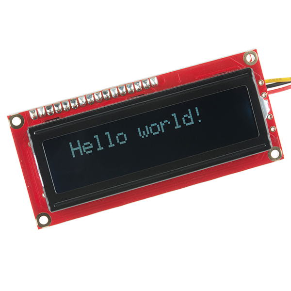
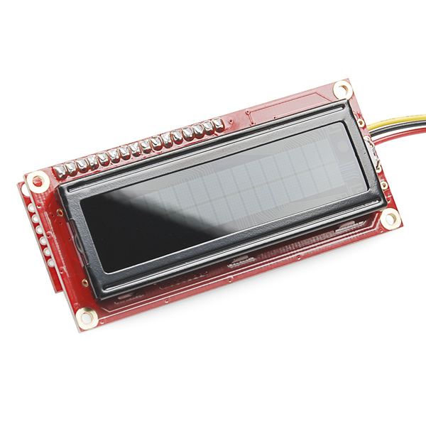
Calling this the "Serial Enabled LCD Kit" doesn't do justice to how cool it actually is. After you've assembled this all-PTH kit, you'll be left with a fully Arduino-compatible development board that just happens to have a white on black 16x2 display built-in.
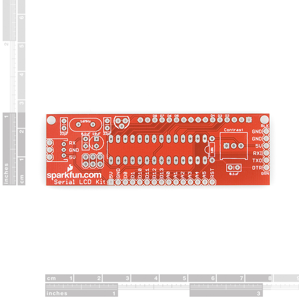
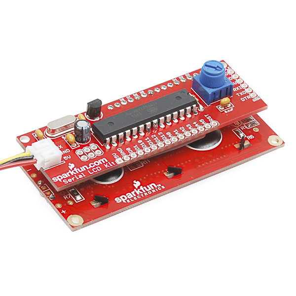
Turns out the ATMega328 is pretty far over-spec for just controlling a parallel LCD so there's a lot of horsepower left over to do whatever else needs to be done. We've broken out all of the unused GPIO pins to 0.1" headers on one side of the board, making this more than just a great kit for beginner soldering but also an awesome development tool for experienced programmers.
In order to upload new code to the LCD Kit via bootloader you'll need an FTDI Basic Breakout and have the Board setting in Arduino on 'Arduino Duemilanove w/ ATmega328.' The uC comes pre-programmed with the SerialLCD firmware on top of the bootloader, so if you just want to use it as a serial-enabled LCD, you won't need to do any programming.
Check the github page below for instructions on how to use the kit. The source code is also hosted over there, if you want to take a look.
- Schematic
- Eagle Files
- Assembly and Getting Started Guide
- Datasheet
- GitHub (Firmware & Design Files)
- Example Code
SparkFun Serial Enabled LCD Kit Product Help and Resources
Core Skill: Soldering
This skill defines how difficult the soldering is on a particular product. It might be a couple simple solder joints, or require special reflow tools.
Skill Level: Rookie - The number of pins increases, and you will have to determine polarity of components and some of the components might be a bit trickier or close together. You might need solder wick or flux.
See all skill levels
Core Skill: Electrical Prototyping
If it requires power, you need to know how much, what all the pins do, and how to hook it up. You may need to reference datasheets, schematics, and know the ins and outs of electronics.
Skill Level: Rookie - You may be required to know a bit more about the component, such as orientation, or how to hook it up, in addition to power requirements. You will need to understand polarized components.
See all skill levels
Comments
Looking for answers to technical questions?
We welcome your comments and suggestions below. However, if you are looking for solutions to technical questions please see our Technical Assistance page.
Customer Reviews
3.7 out of 5
Based on 3 ratings:
2 of 2 found this helpful:
Ultra Reliable LCD
Had it working for 3 years already. It worked for a year on an Arduino ATMEGA328P flawlessly. And after that, it's been displaying the messages of a Raspberry PI Model B (yep, the old first Raspberry PI).
And it is still going strong.
Only complain I have is that mine came set at 4800 bps, but I've been too lazy to make a sketch to set it at 9600 bps
0 of 6 found this helpful:
Poor product QA and poorer service.
The device displays its startup image properly, but the communication does not work: all of the text is scrambled. Running any number of different programs in addition to the Sparkfun example code (https://www.sparkfun.com/products/10097) makes no difference. I found that I was given 2 correct capacitors and 2 unknown ones which I replaced with the correct ones from my electronics bins. Ok, so the device is defective probably due to poor QA (I returned another product a few years ago due to poor QA). The real issue I am having with SparkFun is response time to product issues. I reported the problem on Dec. 2 and it's now the 21st. The latest of 16 emails back and forth indicate "I will look into this for you." Really? What the hell have you been doing for 3 weeks??? Obviously, SparkFun does not know a bleeping thing about customer service. If I don't get satisfaction soon, I'll have to resort to sharing my experience publicly. I'm sure that will really help their business (sarcasm intended).
I'm sorry, you seem to have forgotten where your conversation left off with us. It was mentioned in our first response back to you that we would be happy to assist you. And in our last response that we have arranged a (back ordered) replacement for you.
Your records show a representative explicitly confirmed with you that we will be replacing your parts once they are back in stock. You were issued an RMA number and a back order has been placed for your account.
Today I adjusted your RMA from the exchange to a refund. You will receive your funds within 1-3 business days.
Good documentation, super clear display
This display was especially nice because it is very easy to use and very fast. Although not the least expensive 2x16 solution, you end up with an Arduino core.
I bought one of these approximately 12 years ago. It was a nice display that worked well.
I've recently hooked it up to my Ardu Duemi and it boots up properly when Gnd and 5v (from the arduino) are plugged in. However, it is not displaying correctly or at all. All of the characters are illegible when I load a new sketch into the Ardu.. I'm using "SoftwareSerial" as one of my libraries.
Any help would be welcome.
Thank you, Tim
What logic voltage is this?
Assuming you're powering the LCD with 5V, the HIGH logic voltage will be 5V. You can probably get by with slightly lower voltages if you need -- check out our logic levels tutorial for more on that.
Is it possible to order one of these without the actual lcd?
Any chance of getting just the PCB avail for sale?
Can you order this kit without the display so that you can use a different color or a display with 4 lines instead of 2?
You can order the serial enabled backpack (LCD-00258) pre-assembled and attach it to our basic screens.
Do you offer this board on its own, or the kit without the LCD? It looks like a great kit, especially with the microprocessor 'integrated', but some prefer red LCDs.......
We offer the screens and the backpack separately, but the serial enabled backpacks are pre-assembled. You could always order this kit and one of the basic 16x2 5v screens that we sell in the color that you want.
Different circuit, the prebuilt backpack uses a PIC, so no good if you want to use as an Arduino
If you want to be able to upload your own code to the backpack, you're correct that the PIC based backpack won't work in the Arduino IDE. But you can communicate with the PIC backpacks from an Arduino over serial. Take a look at this example.
Thanks Toni, that article looks like it could be useful at some stage :) As you guessed, I was more making the point about the other (PIC) backpack being different in that you can't program it in the same way as you can an Arduino (even though I don't have an Arduino). Like some of the other people I do have a number of suitable LCD's around and a project I had in mind before seeing this would likely suit this AVR backpack really well, without any other micros, even though I mostly have PIC stuff e.g. ChipKit, Pinguino. Hopefully we'll see just this backpack at some stage, as it's a pretty versatile little board :) Cheers
Is there a possibility in getting the board only or just without the LCD? Have couple of those waiting for to be used, no need for any more, yet :) Or is this the wrong place to ask this kind of question?
Can we possibly get this board by itself or at least with a 20x4 LCD? I know I can purchase the LCD-00258 but that is not the same board. It has a PIC instead of the ATmega328.
I don't know if anyone else had the same problem but it took me hours to fix so I'm posting the solution here so that it may save you time in the future.
1) When you program your microcontroller and the serial enabled display (SED) is attached it is possible that garbage commands are sent to the SED. In this case the baud may be changed, brightness etc. Do not program your MCU while the SED is attached. In the case of the Ardunio it is possible to overcome this problem by using software serial instead of the hardware serial. (see: http://playground.arduino.cc/Learning/SparkFunSerLCD).
2) It appears that more often than not the setting that is changed is the baud rate. However this is not the only setting that can be changed. In my case I discovered that the LCD display type had been changed and caused the characters that were sent to the SED to be displayed from bottom up. IE trying to display the word "Hello" resulted in the "o" being displayed in the first line and first character position while "l" was displayed in the second line first character position. It is possible that the same issue could cause the text to be sent to an out of bounds position and result in nothing being displayed.
I have attempted to solve the issue by using software serial on the Arduino MCUs and ALWAYS setting up my SED in software at start up even if I have previously configured the display.
I hope that this helps some of you.
Just a tip - if you want to reprogram this, but you don't have an FTDI breakout or the like, you can use another Arduino board. Just remove the Atmega chip, and connect the 5v, Gnd, Reset, Tx, and Rx lines appropriately.
I'm trying to do this, but having trouble getting the arduino software to recognize the chip. I'm consistently getting:
avrdude: stk500_getsync(): not in sync: resp=0x00
I think this means the board isn't being recognized. Did you have to change anything in software to get the board recognized? Any tips? Can you sent me an email matthew.berginski [AT] gmail.com
I'm trying to use 4-40 metal hex stand-offs to separate the bottom control PCB from the LCD board.
However I can't screw in any 4-40 thread into the LCD holes. If I try the metal ground points are twisted and nearly stripped off.
What size screws are intended for the LCD board?
Ever heard of metric? I haven't checked, but they're probably M3
Possibly a naive question, but are we missing resistors to limit the current in the backlight LED and the NPN transistor?
The backlight transistor is configured as an emitter follower. So the backlight voltage is Vbe(sat) below the base voltage, and since the base is at a little less than 5V it results in about 4V to 4.2V at the backlight. So if anything the backlight is underpowered and could be driven harder.
My backlight just burned out, so I don't know if I did something wrong or if there is no current limiting resistor!
The trimpot is the resistor set, I believe.
Does this LCD work with the BeagleBone Black, or would the Sparkfun Basic 16x2 LCD be more appropriate if you are attaching it to a BeagleBone?
Is that unpopulated header just above the Sparkfun logo for ICSP? Could I use the AVR Pocket Programmer to program this (after taking the "Red Pill," of course...)? Many thanks!
That it is. Keep in mind that the Arduino bootloader is already on the chip so you can also just use the FTDI header to upload new code.
PLEASE I NEED HELP PROGRAMMING THIS LCD TO DISPLAY VOLUME FROM A MINI AMP I BIULT HELP!!
Loading code to the chip is not a problem here but Im not able to load a code AND make the LCD work with it! Has anyone worked that out?
So is there a way to reset this? I just get garbage on the screen. I have searched the entire internet and all the sketches I am told will reset it don't work.
I have a love hate with this thing. The input serial port is connected directly to the same RX line used to program over FTDI. It is SO easy to accidentally change the baudrate and render the screen seemingly useless from another microcontroller.
If you can't seem to communicate with it, you have a few options. First, download the SerialLCDSourceCode sketch, we are going to modify it Option #1 Paste this as the very first thing in void setup EEPROM.write(BAUD_ADDRESS, 4 ); // This resets the memory to 9600
Option #2 Delete void setBaudRate function completely!
1) Delete the function void setBaudRate (at the very bottom) from bracket to bracket 2) Then look in void loop and find the line that says // baud rate control then delete that else if statement from bracket to bracket 3) Last, add Serial.begin(9600); as the first line in void setup
Sure, you will have to manually set the baud rate but now you can upload without fear of your baudrate changing accidentally!
Option #3 is more of a preventative thing.. import the SoftwareSerial library to the sketch and do away with using the hardware serial (but you will lose a pin unfortunately)
Hi! This is my problem, when I connect the lcd on arduino, the screen of the lcd turn on, but dont show no one message. I tried the example code hellow world but dont show the message on the lcd! The lcd light just only stays on... Please help me!
I have a problem with my kit. It was working perfectly until I connected a servo to the arduino I'm using with it.
The servo started gittering and all of a sudden the screen started displaying a bunch of funny looking characters. (Chinesse looking, sorry for my ignorence in the matter)
The the characters are updated from left to right, one line at a time at a rate of around 10/second witch is the rate Im updating the LCD I tried another arduino board and the same thing happens, but the characters this time are A,E and //, really puzzling to me.
I downloaded the files (Serial-LCD-Ki-master) from Github, conected the FTDI and updated but I still get the same...
Also tryed different baud rates... nothing
Any ideas? Thank you!
Was looking for an enclosure to fit these 2x16 LCD's and found an "MDT-65" ABS plastic box on eBay that fits perfectly. Seller has them available in both black and white and the mounting holes line up perfectly for this display with enough room to mount the entire assembly. Use M2.5 self-tapping screws to attach the LCD PCB to the enclosure.
I'm trying to hook one of these up to an XBee Series1 Pro(Coodinator) to print responses from remote XBees(Endpoints) but get what looks like very dim Japanese characters. Has anyone tried this, or seen any articles on such?
I'm using the new XCTU software to test sending the following API frame, which should tell the device to show the splash screen: 7E 00 0D 00 01 00 13 A2 00 40 53 5F F1 00 FE 1E 4A
Thanks for any info. Paul
I'm having trouble with contrast on mine. The only way for me to have anything displayed is for the trimpot to be turned all the way one direction, and it still isn't very bright/contrasty. It seems like the pot should be somewhere in the middleish and turning it too far should make the display just show boxes, but mine won't do that.
So to answer my own question, the problem was that I was using the 3.3V FTDI instead of the 5V one. Once I hooked up the display to 5V, I got good contrast.
I'm so sad I couldn't get home in time to buy one of these while it was on the cyber monday flash sale. I wanted one at that price so bad. Oh well, it is still a pretty good deal without the extra 40% off, I will probably buy one somewhere down the road.
https://github.com/mr1337357/Serial-LCD-Kit I tweaked the firmware a bit and added support for the GDM1602K's custom glyph mode.
Can you recommend a different library than SoftwareSerial? It uses extra memory, wastes a pin and fights with other instances of itself. Since this is a receive only device, a much simpler version should be possible.
I found this little gem on the arduino forums: http://forum.arduino.cc/index.php?topic=112013.0 I will check it out and report back
Dear everyone, I have a serial LCD-10097 interfaces with Arduino Mega 2560. When I run a sample code to test the LCD, it does not seem to line up as the position 1, line 1, or the position 1, line 2. Here is the sample code I got from Sparkfun;
// SparkFun Serial LCD example 2 // Format and display fake RPM and temperature data
// This sketch is for Arduino versions 1.0 and later // If you're using an Arduino version older than 1.0, use // the other example code available on the tutorial page.
// Use the softwareserial library to create a new "soft" serial port // for the display. This prevents display corruption when uploading code.
include
// Attach the serial display's RX line to digital pin 2 SoftwareSerial mySerial(3,2); // pin 2 = TX, pin 3 = RX (unused)
void setup() { mySerial.begin(9600); // set up serial port for 9600 baud delay(500); // wait for display to boot up
mySerial.write(254); // cursor to beginning of first line mySerial.write(128);
mySerial.write("RPM: "); // clear display + legends mySerial.write("TEMP: "); }
int temp, rpm; char tempstring[10], rpmstring[10]; // create string arrays
void loop() { temp = random(1000); // make some fake data rpm = random(10000);
sprintf(tempstring,"%4d",rpm); // create strings from the numbers sprintf(rpmstring,"%4d",temp); // right-justify to 4 spaces
mySerial.write(254); // cursor to 7th position on first line mySerial.write(134);
mySerial.write(rpmstring); // write out the RPM value
mySerial.write(254); // cursor to 7th position on second line mySerial.write(198);
mySerial.write(tempstring); // write out the TEMP value
delay(1000); // short delay }
Please help me.
Thank you very much. Tony
Dear all, For this serial LCD to work correctly with my Arduino Mega, would my Arduino software version 1.0.5 work correctly between the Mega and this serial LCD? Please help! Thank you, Have a great day!
This is a great product. It was fun to build, easy to program, and works great.
My backlight seems to have burned out. How can I fix it???
you guys should sell these: http://www.techsupplies.co.uk/epages/Store.sf/en_GB/?ObjectPath=/Shops/Store.TechSupplies/Products/AXE133Y they are easier to program and come in various sizes
Can I use an RGB lcd with this kit and have it control the color ? I was thinking about using this one RGB LCD
This is perfect for a project ive been working on thanks sparkfun. cant wait for mine to show up!
Youv could get rid (optionally atleast) of the potentiometer and offer digital contrast by plugging OC1B PWM output to RC filter (220ohm + 4.7u? or something) and that to contrast pin. Works in my ATmega328 + LCD-based device but I have OC0B and OC0A doing BL LED PWM and contrast and Port B as 8-bit LCD interface and no xtal (which I see you want for serial)...
Success i have completed my homemade wirewrapped version of this. Functions perfectly.
Howdy TechoJunkies!! I am currently building one of these from scratch and it is eventful.. The problem i am having is sending commands to the backpack. I.E. clear, scroll, etc. it just echos them on the display?? I am using the serial terminal in the arduino ide.. Ideas.? I am using the code that is on the github page with no alterations.. built the display backpack per schematic. Curious??
You need to send the commands as bytes, and sending them from the IDE serial window sends them as ASCII characters. Try sending the commands via the Arduino board itself if you can, or try using a different terminal program such as CoolTerm, which allows you to choose the formats of commands that are sent.
Thanks for the wisdom.. I actually built this from identical components on waferboard with wirewrap 33 ga white wire, Look like art.. PITA but fun. ant that what hackin's about.? Will post a picture when finalized if un's want to scope it out.. Worked of a picture of your bare pcb and schematic.. Fun trying to look at it in reverse in Eagle..
Easy kit to solder together, I've got very little soldering experience, I was blown away by how much easier this was to solder with the correct solder than the beastly large stuff I've been trying to use on everything else. It still took me about 45 minutes to get all together, but I was being pretty meticulous and checking pretty much every joint.
My desoldering skills need work though, I forgot to mount the 10k resistor until after I soldered the headers to hold the LCD to the control board. It seems in trying to get them apart I've destroyed both boards :( Glad I picked up an IC socket so I can at least salvage the ATmega 328 by just pulling it out. Practice my obviously lacking desolder skills on the rest of the components and eventually order another of these to play with.
Has anyone directly powered this kit using a 5V wall adapter (https://www.sparkfun.com/products/8269)? Is it as simple as connecting the ground and VCC leads from the JST connector, perhaps using a barrel jack adapter (https://www.sparkfun.com/products/10288)?
Anyone have experience using this kit in a wall powered setup?
Hi, any chance of getting a firmware update for I2C and SPI interface aswel? it would be great!
The only complaint I have is that both interrupts are taken by the LCD(D2 and D3 on the ATMega). Not a problem unless you are using the kit as a stand alone unit to read and display RPM.
Same problem here. It would be nice, if this could be implemented in a future design. Apart from that, It is a great board, which I use in several projects.
Can someone clarify the use of both interrupts? Since there's an ATmega328 uC piggy-backed on this display it's not clear to me if the interrupts used belong to the onboard ATmega328 or to the Arduino to which this display is wired.
If it's the host Arduino's two interrupts, is this a limitation of the SoftwareSerial library used to communicate with the display or something else?
I was trying to write to the display from within an interrupt service routine and doing so locks up the host Arduino so I'm guessing it's the host Arduino's two interrupts. If this is the case, it's too bad the compiler preprocessor doesn't catch the overallocation of interrupts.
has anyone got this to work with lcd smartie, or another program like it.?
Hi, can someone explain this to me
Quote: "In order to upload new code to the LCD Kit via bootloader you'll need an FTDI Basic Breakout..."
Is that to change the fonts on the LCD display or GUI ? Or is it needed to what type of data to display on the LCD?
I love this thing. You can use it for rapid prototyping and then switch to a native interface for the LCD later on... and you still have a use for the serial module as all the pins (or at least most of them) are broken out on the headers. Having a header for the FTDI breakout board is great as well for quick testing... you should like to it at the bottom. Overall a really great product!
The "Serial LCD Kit - retail" (same kit, different packaging), has a quite good tutorial by Jimbo. Strange there's no link to there from this page, Serial LCD Kit Landing Page http://www.sparkfun.com/tutorials/289
Hi. I'm having trouble with this device. I am sending serial.print text to the LCD, but it seems pretty erratic. I wonder if it was damaged when I soldered it to the board. There is not chip holder in the kit. Sometimes it does not power up:( I'll have to check it out for bad connections. Should the device should respond to serial.print similar to the way serial monitor works?
i like this kit allot but it has its challenges, i am trying to figure out how to get the back light back on, it seems to have gotten a command to turn it off. and not much seems to want to turn it back on. the other thing i would like to know is that, can i reflash it with a different firmware using a ftdi without taking the lcd off.
I have ported LiquidCrystal library for use with the serial LCD you can look at my code here. Still working on finishing all the documentation. But putting up for now hopefully someone will find it usefull.
http://arduino.cc/playground/Code/SerLCD
-Thanks
can i buy this then get a 20x4 lcd for it? or is their a kit like this with a 20x4 already?
its awesome! not for convert a lcd to serial, but because you have a arduino in a LCD. maybe sparkfu can sell this as "LCDuino Arduino on a lcd"
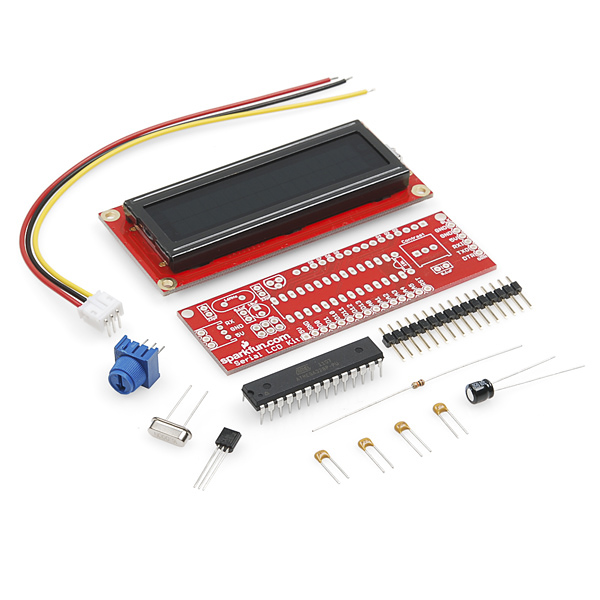
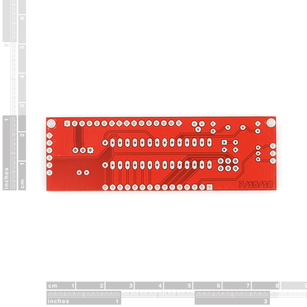
Are there any instructions or tips for putting this together, or can I just infer where stuff goes by looking at the images above and the labels on the circuit board? I'm not particularly great at reading schematics.
Thanks,
Adam
These things are just the bomb. Great price for what you get.
I confess I haven't been using them as intended - once I have a project all figured out with the arduino and the breadboard etc I order one of these and write my sketch to it. Any time I am using an arduino and the liquidcrystal library and I am ready to go from prototype to finished project, this is my go-to kit. Just wish it included a socket for the IC.
I've got it driving my diy networked home thermostat: http://bit.ly/eCzVIW
Cheers!
This this is pretty awesome, but would be even more awesome (awesomer?) if you could upload custom characters over serial. The LCD itself seems to support this, but the Serial LCD firmware does not.
It shouldn't be too hard to add (after all, the LiquidCrystal library it uses has a function just for this). I guess it's finally time for me to get an FTDI Basic.
Not to reply to myself again, but I updated the firmware and it now can upload custom characters to the LCD's CGRAM. I made a post about it with some example code and the code for the updated firmware on the forums
I wonder if SparkFun could add this to their git repo.
I wonder if you can do this by just sending the instructions to do it as if they were characters to print. Provided none of the data is something the ATmega328 will intercept as an instruction to change the baud rate or something.
edit: Evidently not, the ATmega328 just puts whatever you send outside of the commands listed on github into the LCD's display RAM.
My display unit LCD-10097, has accidentally become corrupted. In particular the back light has turned off and since I have not yet been able to communicate with the unit I am unable to debug my code. Is there a way to reset the unit to defaults as shipped?
Hum, you might want to talk to tech support. I don't think there's a reset, but you can surely reprogram it. See what they have to say, techsupport@sparkfun.com
I would be really cool for the next revision to include the capability to run off of 3.3v logic.
I have creatively soldered a logic level converter to the backpack using some of the broken out pins (leaving the standard three wire port alone) and now I can hook it up to my Fez Panda with 4 wires: 3.3v, 5v, Data (3.3v) and Ground.
A better solution might be to eliminate the 3.3v reference feed with a voltage divider, or just get logic that can handle 3.3v from the get-go.
So ideally I would be able to feed it (through the standard jst 3 pin connector) 5V, Ground, and Data at 3.3+ V.
That would be nice.
I've managed to alter the setup of the Serial Enabled LCD Kit and now I cannot read anything of the diaplay or anything else.
How do I reset it for use at 6900 baud and everything else? What should I send as command (0x7C - ?).
Can anyone help me with a set of code for reseting the backpack, e.g. comm 9600 baud etc. Please?
Have you tried 0x81 followed by 0x04 - the github page seems to indicate that that will reset the baud rate to 9600 - however you will need to know which baud rate it is currently running at.
Have you asked this in the forums? That would be more conducive to a troubleshooting dialog.
@ AdamTolley
I'll try 0x81, 0x04 next time. Hope it works, I'll write code to try the different baud rates.
And next time I'll use the forum instead of here. Cheers, Teit
Had to really dig hard to find out how to use this and the sketch I did find had many errors where special commands were sent which required it to me mostly re-written. Learned a lot however. The documentation is really lacking. For instance, no mention of how to send and display special characters. I would also like to see this kit without the LCD for those of us that would like to use a different color or have and LCD already or have messed up the PCB. Lastly, there is no assembly instructions and the photos don't show many details that you need to see.
https://github.com/jimbloom/Serial-LCD-Kit/wiki/Serial-Enabled-LCD-Kit-Datasheet
Probably a very noob question but can this easily be interfaced with a serial port on a computer? and is it HD44780 compatible?
It could be interfaced in some way using the FTDI Basic. Not sure about the HD44780 compatibility though as I don't know what that is. :D But the onboard code is basically Receive stuff from Serial Monitor -> Print stuff from Serial Monitor -> Wait for more stuff from Serial Monitor, so all you need to do is send it serial commands and it'll do its thing.
Good morning all. I'm still looking for help sending commands to the serial backpack. I found the commands on the github page but not how to send then to the device. Art
If you go into the Arduino IDE and set the board to "Duemilinove or Nano w/ ATMega 328" then bring in the Serial Monitor and type in the commands (using the correct baud rate of course), that should work. Oh, and you probably know this, but make sure to plug in the board to the computer BEFORE opening the IDE. :]
Thanks for the reply. I've been there looking for sample code and all I could find was the code for the backpack itself. I dl'd and install the new code into the backpack but I don't understand how to sent the special commands to do things like clear the display or set the display for 4X20 I'm using NewSoftwareSerial to connect to the backpack and I can print "Hello World" but when I try to send a special commands it either prints garbage or nothing. Art
Does anyone have some sample Arduino code that make use of the LCD backpack? I can't figure out how do things like set the the cursor to a location or how to set the display to 4 X 20.
Thanks
Art
Click the github page link above.
I like the fact that the SDA/SCL pins are broken out. (same as analog pin 4 and 5) So rewriting the code could open up I2C interface posibilities aswel. However that nokia 5110 display looks like a nice bargain at just under 10 dollar. Unfortunately it needs 5 pins to be fully functional. :( Tough choice.
An ATmega328 seems like massive overkill for a serial-LCD converter, but it's nice to have all that extra storage for customization, and it's probably easier than stocking mega8s just for this (and probably not a big price difference).
That's exactly it. We would just rather keep our stock to just ATMega328's. We go through so many, if you knew how many, your head might explode.
Imma guess... 1,349,297? .3?
Is this arduino compatible - or is it more native code? What cable / software do you need to program it?
You can use the Arduino IDE with this, and just use a simple FTDI basic for programming.
+1 for the source?
I'm keen to build one!
Check the github page, it has the source on it. We're moving over to using github to host most of the files since we can easily update from there.
Also, It looks identical to the white on black listed below in the related products. It's the same exact screen.
ditto Thanks RobertC.
Thanks!
Is the source code for the ATMega328P available?.
Does this unit work at 3.3V or 5.0V?.
+1 for using an Atmel chip; +1 for breaking out extra pins.
Including a picture of the "white on black" characters in action would be handy. (This has been done for other LCD products).
Did we ever figure out if this supports 3.3v?
I have 5V available to power this, but I want to know if I need a Logic Level converter for the serial connection to use this with my FEZ Panda.
5V, it might work barely at 3.3v, but I don't think it will be enough for the backlight.
What about just 3.3v data? (using 5V Vcc)
Guess I better splurge and get the 2$ logic level converter.
Has anyone added a button or a joystick onto kit, to then scroll through what text was sent to it from their arduino?
I haven't heard of anyone doing that particular hack on this product, but it probably wouldn't be that hard to implement.