- Home
- Product Categories
- Flex / Force
- Load Sensor - 50kg (Generic)

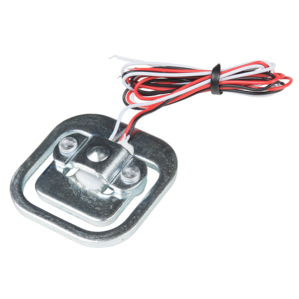
This load sensor, sometimes called a strain gauge, is the same one found in digital bathroom scales (you know, the ones you use in January for your New Year's resolutions, and then forget about a month later). This sensor can measure up to about 110 pounds. Check the video below for a simple explanation on how these work and how to use them.
- 30cm cable length
Load Sensor - 50kg (Generic) Product Help and Resources
IoT Weight Logging Scale
May 9, 2018
This tutorial will show you how to make a scale that logs your weight to a custom website on the Internet. The principles can be extrapolated to any type of data.
Getting Started with Load Cells
June 11, 2015
A tutorial defining what a load cell is and how to use one.
Load Cell Amplifier HX711 Breakout Hookup Guide
July 22, 2016
A hookup guide for the HX711 load cell amplifier breakout board
Resources and Going Further
Here’s some additional information on using this load sensor:
Quarter, Half Bridge and Full Wheatstone bridge: Bridge strain Gauge Load Cell Configurations [ http://www.transducertechniques.com/wheatstone-bridge.aspx ]
How to wire up a 3-wire load cell strain gauge and an amplifier [ http://electronics.stackexchange.com/questions/18669/how-to-wire-up-a-3-wire-load-cell-strain-gauge-and-an-amplifier based on the ProtoPic demo http://www.youtube.com/watch?v=Bm6ANv93YjM ]
Robotistan.co: "Load cell usage - Load cell using 3 wire load sensor" [ https://translate.google.com/translate?hl=en&sl=tr&u=https://robotistan.freshdesk.com/support/solutions/articles/12000009562-load-cell-kullan-m-load-cell-using-with-3-wire-load-sensor&prev=search ] has an example for wiring up a quarter Wheatstone bridge, HX711, an Arduino Uno.
3D Model
Check out the user submitted 3D model of the load cell:
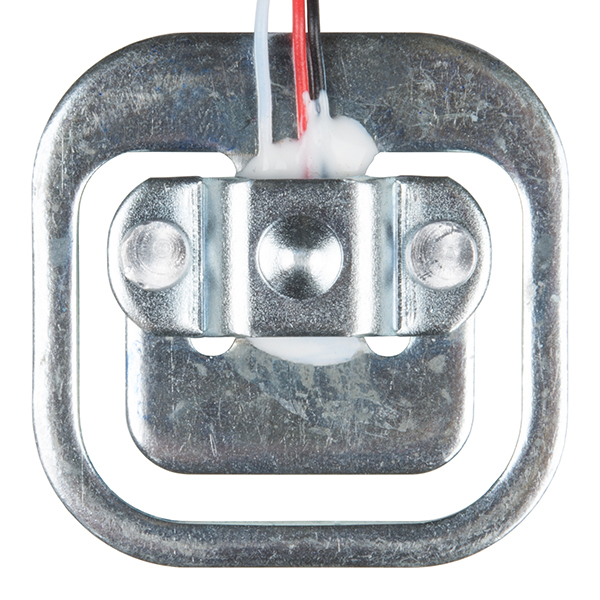
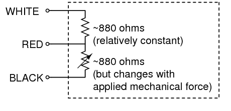
Color codes for the 50kg load sensor
White and black are the outer terminals with red being the center tap. The picture below will give you a good idea what the inside of the load cell looks like. Our load sensor should measure 1000 ohms between the red and white or black wires and 2000 ohms between the black and white wires.
 )
)
Core Skill: Programming
If a board needs code or communicates somehow, you're going to need to know how to program or interface with it. The programming skill is all about communication and code.
Skill Level: Rookie - You will need a better fundamental understand of what code is, and how it works. You will be using beginner-level software and development tools like Arduino. You will be dealing directly with code, but numerous examples and libraries are available. Sensors or shields will communicate with serial or TTL.
See all skill levels
Core Skill: Electrical Prototyping
If it requires power, you need to know how much, what all the pins do, and how to hook it up. You may need to reference datasheets, schematics, and know the ins and outs of electronics.
Skill Level: Competent - You will be required to reference a datasheet or schematic to know how to use a component. Your knowledge of a datasheet will only require basic features like power requirements, pinouts, or communications type. Also, you may need a power supply that?s greater than 12V or more than 1A worth of current.
See all skill levels
Comments
Looking for answers to technical questions?
We welcome your comments and suggestions below. However, if you are looking for solutions to technical questions please see our Technical Assistance page.
Customer Reviews
4 out of 5
Based on 6 ratings:
2 of 2 found this helpful:
Works great once figured out
It does take some time to understand how to wire properly. Read the guides, then read them again. Trust me, everything you need to know is there. I used an OpenScale board to connect and manage everything - very happy with results. You do need four of these arranged in a square on a platform, a bit of solder into the open scale board, and a USB cable/host is all you need. Wrote some python on a RPI to make this into a handy little IOT scale.
9 of 10 found this helpful:
Works fine, but I had to dig around in the documentation a bit
I built a dog weight scale using 4 of these, a Load Combinator board, a Load Cell Ampllfier, and an Arduino. It worked and gave good results the first time I turned it on.
This page could use a little more documentation on two things: 1) how to mechanically mount the thing. You must mount it with a cutout below it so the "T" bar is free to bend below the "C" frame. 2) a brief schematic and instructions on how to figure out which wires are which. As it is, the Black, Red, White colors sort of match the Red, White, Blue colors of the Load Combinator. It would be easy to mention: to test the wires measure the resistance between each pair. The wire with the lowest resistance is the "red" center tap. Then measure the other two wires resistance to the Red wire as you push on the sensor: one wire will show a changing resistance, the other won't change much.
I found all this information buried near the bottom of the hookup guide. It would be helpful to reiterate it here for people who don't plan to use the load combinator.
2 of 10 found this helpful:
Totally useless, poor documentation, poor everything
There's only ONE way to use this thing, according to SparkFun and that's by connecting four of them to a combinator and load cell amp. I would never have purchased the thing knowing that I would have to spend $40 instead of $10.
It's not as simple as it should be and there is next to no documentation or relevant help for this sensor. I would not recommend it to anyone. AND PLEASE DO NOT GIVE ME A LINK TO YOUR USELESS "Getting Started with Load Cells" PAGE.
I'm sorry you're having trouble with this product. Like every load cell, it requires an amplifier. However, as is laid out in the HX711 Hookup Guide, this three-wire load sensor requires 4 units and a combinator board.
0 of 4 found this helpful:
Confuse
I still am unable to figure out how it works...
There's a good tutorial here to help you - https://learn.sparkfun.com/tutorials/getting-started-with-load-cells
Why I like the Load Sensor
It's a small pressure sensor which I can use with my arduino or even with a professional project. Yet the best part is that it can handle up to 50Kg. It is small but robust and I can use it outdoor
Great product, just had to search around on how to mount them!
This is a good product and the set up guide is very descriptive, one just needs to read the full article. However, the guide has really has no description on how to mount the load sensors. Here are some videos and articles that I found very helpful in regards to setting up the load sensor (even though the video doesn't use the amplifier, the combinator board and uses different code then is found on the sparkfun website, it still gives a great overview of how to set up the load cell and why it works - this is also shown in the complimenting article), and for mounting the load cell (a short video on how to mount them, and the website where the 50kg load cell bracket 3D sketch can be found).
Set up video and article:
https://www.youtube.com/watch?v=LIuf2egMioA
https://circuitjournal.com/50kg-load-cells-with-HX711
Mounting video and sketch:
https://www.youtube.com/watch?v=aTn74FyhrXI
https://www.thingiverse.com/thing:2624188
Hopefully this helps!
I found the Load Sensor a bit tricky to mount properly, so I eventually designed a 3D printed part to hold it to a wooden support block. It's loadsensorholder.FCStd/.stl, part of my Dog Bed Weight Scale github at https://github.com/bneedhamia/CurieBLEWeightMonitor
This is based on the Strain Gauge? How can i check some electrical resistance strain gauge formula couse i need that to compare efficiency.
What kind of precision can you get out of these sensors if you had four of the hooked up through a combinator to your HX711 amp board? Can you get down to ounce or sub-ounce precision? I'm thinking I'd like to use them to detect changes in volumes of liquids but I would need approximately ounce precision.
Does anyone have any photo examples of mounting these? Like previously stated, they're tricky to attach.
This product needs to be upgraded to at least skill level 4. It's useless right out of the box without extra components.
A+ on the handle selection, by the way.
Hi we've made a Video blog post with an example schematic for those who are having issues getting these to work:
http://protopicelectronics.wordpress.com/?p=39&preview=true
Cheers!
Link to his blog is borked. Direct youtube link
You can also use a INA125P to get a usable value. Instructable and a useful schematic
Purchase two load sensors to create a wheatstone bridge. White wires go to V+, Black wires to V-, red wires go to pin 6 and 7 of the INA125P. Using a 10ohm resistor will give you 0V-5V (or 5V to 0V if you wire it backwards)
One thing that confused me was applying force to the sensor. You have to suspend the sensor from the outermost edges of the "E" shape and then press down. Simply pressing downward on the top of the sensor laying on your desk won't do anything since it doesn't flex the portion of the sensor where the resistor is mounted.
You should reverse one of the two sensor's white-black connections so the increased deviations due to increased loading unbalance the full wheatstone bridge. Otherwise, if you hook them up white-to-white, black-to-black, the bridge will sense the difference between the loads, rather than the sum of the loads.
In the video, they don't load the second cell, so it doesn't matter, but if you want 100kg from adding both cells, reverse one cell's excitation.
If you want to add to 200kg capacity from four of these cells, its possible, but trickier: Hook all four together in a ring, white-white and black-to-black, then excite the network with two opposite reds from the ring, and sense off the two intervening reds.
Thank you for this comment. I'd been staring at the wheatstone bridge arrangement for a while and utterly failing to comprehend it — thinking along the lines of "if all four sides of the bridge simultaneously drop in impedance because the weight is balanced across all the strain gauges, surely the resulting 'sense' voltage remains precisely the same?". With your comment, the penny finally dropped. I don't know if I was just being particularly stupid today, or the documentation elsewhere could do with being a little clearer :)
Great video! Thanks for sharing!
For those of you who are having issues getting any type of usable value out of these, we wired up the following:
White to 5v, Black to gnd, Red to Input on OpAmp (BOB-09816) with the in-series caps removed, OpAmp Vcc to 5v, Gnd to Gnd and Out to Analog 0 on the Arduino.
The variance isn't a huge amount, but it does give you values you can work with.
I need to go this route, can you detail which caps exactly that you mean? Thanks!
I second this. there is no documentation anywhere on how to "remove caps" or even where the caps are located.
I'm using a TI Burr-Brown INA125 OpAmp and with the right gain you can get about a 3V range out of the sensor. The datasheets are easy to read and have the circuit you need for a sensor like this already laid out for you. If you're going to buy one of these, its definitely worth taking a look at the INA125.
What is the "right gain"? I'm using a TI INA126PA with approx 150 gain and getting nothing. Is there some magic about how you mount these things to get some small flex in the metal? Any ideas are appreciated!
Hi , I recently purchased two sensors and reading the comments I 've gotten them work in the following ways :
1 - . Black - Vss White - +5 Vdc Red - Signal
Then I measure the voltage difference between the red wires and increase as the effort mV. If I press a sensor gives a positive value and if I pull the other gives a negative value. Right now, the two are at rest and the multimeter will mark me 0.6 mV, I suppose it's an error rate of internal resistance.
2 - . First sensor : Black - Vss White - +5 Vdc
Second sensor : White - Vss Black - +5 Vdc
The reading remains at rest 0.1 mV , but pressing either always gives me a positive value.
I'll try to get a Ampop to amplify the signal through the red wires and do some tests , what I get is , according to the scheme of the Wheatstone bridge that says to calculate an unknown resistance is needed to know the value of the other three is attempting to use a single sensor but doubt is the temperature compensation , work environment where sensors will suffer sudden temperature changes , so will be at 5 ° C in winter to 40 º C in summer.
I will try to get the exact given temperature.
regards
I have four sensor that appear to be very similar (three wire load sensors) from a bathroom scale. I've wired them as if they were each 1/2 wheatstone bridge (using the red wires as the signal) with Back = VSS, White = VDD (3.3v). This gives me two opposing wheatstones. Each pair of signals (red wires) is read by a differential amplifier and fed into an ADC. They are placed back into the bathroom scale frame and set on the floor. Their differential readings for each pair are: -0.00037500 -0.00000000
with 80 lbs placed on the scale they read: -0.51137500 -0.00075000
I've had one of the sensors out for inspection and placed it back into the scale, I'm assuming this a major contributor to the descrepencies at zero weight placed. Either way, does this sound like correct placement? If so, why would a scale utilize two wheatstones? Thanks for any insight...
To use both of the sensors in a wheatstone bridge, you must reverse the polarity of one sensor.
Sensor 1 black wire and Sensor 2 white wire on +5VDC.
Sensor 1 white wire and Sensor 2 black wire on GND.
Then you can measure the voltage difference on both red wires, and the voltages from both sensors will add up. If it's negative just reverse the polarity.
Hope this helps... :)
Q: can this precisely sense ounces?
I ordered two of these load cells, and according to earlier comments, one of these load cells is just "half" a wheatstone bridge. How would I go about making two of these into a full wheatstone like in the tutorial? Anyone have schematics? Even if you make a full bridge out of it, am I supposed to use one of the load cells as a passive resistor?
See my response to RandyF above. Basically you arrange the two in parallel (white-white-Vin, black-black-Grnd, read voltage across the red). You'll probably want a differential amp as well. Also, the final output is pretty noisy, so you might want to filter it with a quick low-pass (If I remember correctly I used a cutoff somewhere between 20-40Hz).
Hi, Quailb!...So if I understand correctly, you placed 2 of these load cells in parallel (white-white(Vin), black-black(grnd))and placed the diff. voltage of the red wires into the AD620 (gain 1000) and the output of the aplifier into an RC filter to eliminate some noise, right?...My question would also be how did you physically managed to measure the weight of a pen?...I mean, did you just placed the pen on top of one of the 2 load cells you used or did you used something like a plate on top of both the load cells and placed the pen in it? In other words...are both load cells used for measuring or do you measure just with one and the other is just for compensation?...Thanks for your reply :)
I just wrote out a (lengthy) response to Gizmoguy explaining things in more detail, so you might want to check that out, but it sounds like you get the circuitry. As for sensing, just use ONE of the sensors. The other is just there to balance the Wheatstone bridge. And actually, because of the nature of a Wheatstone bridge and the fact that the two sensors behave the same way, applying a load to BOTH sensors would completely cancel out the signal. If you have the circuit wired you can see that pushing on one sensor will result in a positive Vout while pushing on the other will result in a negative Vout. Pushing equally on both at the same time will give you nothing because you're keeping the bridge balanced.
Now I can think of some situations where you might use this behavior. For example, you could have a board or something supported on each end by the two sensors. Then a balanced force applied uniformly across the board or directly in the middle would lead to no voltage change, while an uneven force distribution across the board would lead to either a positive or negative voltage change depending on the side.
As for the actual mechanical application of the force to the sensor, you might have to get a little creative. For my application I ended up gluing a nut right onto the little round nib and then screwing a bolt into it, but there are definitely other (better) ways depending on your application.
Qualib, if you swap the excitation of one of the cells and you can use the bridge to add the loads.
Looking for load cells? Yes you are in the right place to buy load cells. For comparison for load cells click here <a href="http://www.sensomaticloadcell.net/product-category/tank-weighing-load-cell/compression-load-cell/">Compression load cell</a>
do you have a circuit that test the load sensor if it is functioning or not..? btw i am only using an arduino Uno... tnx
Hello, what is the minimum force this sensor will detect?
Thank you!
would ferrite beads work to suppress some of the noise? And what ferrite bead would you recommend? (Btw im a noob)
Hi,
I'm in the process of creating a posture chair project which incorporates this sensor to measure the weight of the person as well as triangulate the position on the chair to make sure they are sat flush with the back of the seat to keep their back posture. However I am struggling to find the best way to mount this sensor to the under carriage of the seat. any ideas?
Has anyone used these sensors in tension? is it possible to re-configure them somehow to do so?
The price is certainly right to give it a try. With careful calibration, if it's good enough for human bodyweight, I feel like it's good enough for my purposes as a biomechanics researcher,
Would love to design a Load Cell / strain gauge eval board maybe with datalogging and USB (OpenLog + op amps + shunt resistors?). If I design it, I will happily share. If something like this exists already, I would happily buy it, too.
Does anybody know who the manufacturer of this device is?
Can anyone detail the best way to attach a platform to this device? In the video the scale has a setup with the metal piece and plastic casing. Is that available, or is there something simpler you can attach to the end of the load "diving board"?
please show the strain gauge circuit and which one is a temp compensator. Also how to assemble a 4 load sensor wheatstone bridge circuit-arduino system
Thanks
I think it isn't actually a temperature compensator, it is a second strain gauge, with one in tension and one in compression when the base of the gauge is supported on the outer ring, and force is applied on the center nib. Then the top surface of the center bar is in compression on the end towards the rivets, and the top surface of the bar is in tension on the ends towards the wires.
To do 4 cells, you hook them up in a ring, white-to-white and black-to-black, then excite with two opposing red wires, and sense on the intervening two red wires. The wheatstone bridge would then have two resistances on each branch between the reds, with tensions on opposing diagonals, and compressions on the other opposing diagonals. Load on any of the cells would unbalance the bridge constructively, with 10V excitation giving about 45V1mv/V = 20mV of signal at full-scale of 50kg*4.
This is a 3 wire Sensor. In the video they use a 4 wire sensor.
Do you have 4 wire types as well?
I really need some help! I am trying to find someone who can create me a load sensor and reedswitch combo which measures force and counts the reed switch over time. If you think you are the man/women please contact me at stuhr727 at yahoo.com, thanks!
I want something similar to this for an alarm, to put it under a mattress in order to check if the person woke up. 1) will it support the weight of the mattress and the person? 2) is it too big that it can be felt by the person sleeping?
thanks in advance
1) yes (im going to put it under my bedpost but if you dont have carpet be careful) 2) no (its very small just look at the picture its about 1in by 1in). I saw this when looking for a load cell for the same thing so i could wake up on my own for college. Get the tea5767 if you want radio, its small and has great sound quality.
Like others here, I'm working on an arduino based data-logging scale. I've been reading up on load sensors and the sparkfun ADC tutorial, https://learn.sparkfun.com/tutorials/analog-to-digital-conversion to understand this. I thought I might post what I've learned and try to get feedback on the pitfalls, especially for the benefit of absolute beginners, like myself. I also found this to be informative: http://www.aandd.jp/products/weighing/loadcell/introduction/pdf/6-1.pdf
First off, the 10 bit ADC on board the Arduino means that the maximum resolution from the Arduino is 110lbs/1024 (10 bits) = 0.107 lbs/4.88mV per step. If you need higher resolution, you'll need a separate ADC. Also note that this is different from the accuracy of the sensor.
Second, at full load, 110 lbs, with 5V excitation voltage, this sensor outputs 5mV. This means that without an amplifier, your arduino will probably read the analog pin as nearly zero, even at full load. As I understand it, you need a gain of 1,000 V/mv or 120 dB to amplify the voltage such that 0lbs = 0V and 110 lbs = 5V. Have I got that right?
Third, the comprehensive error in this sensor is .05mv/V or .25mV for a 5V excitation circuit, this translates into an error of 5.5 lbs.
Finally, from my reading, it looks like the voltage may vary on the arduino analog pins, so you need to be cautious with your calculations that when you convert the proportion to a weight that your proportion uses the correct reference voltage. Can someone point me to a reference for that?
we have successfully interfaced this sensor and display the weight on Android mobile, http://ethicstech.in/aw/
For anyone trying to build a somewhat precise scale with this sensors please DO NOT use them. Their accuracy and repeatability is very poor, and the slope and offset varies a lot from sensor to sensor. I think you are better off hacking a body weight scale.
If you're still interested, I used the following setup: 4 of these hooked up independently to an INA125 instrumental Op-Amp with about 10-20 ohms of resistor gain (depended on each sensor). A 5th sensor acted as the other half of the wheatstone bridge for each of the four load sensors. For each sensor I calculated an offset and a slope with 4 known weights, with linear fitting. Every output was connected to an Arduino analog pin, and I was averaging 10 samples before adding the weight of each sensor. I managed to get about 2kg of error over a range of 0 to 20kg, but that was way more error that what we needed.
from data spesification, is this sensor can only measurement 40-50kg only? why can i use this from 0kg?
Here is the video of me using this sensor to detect the location of CG of a person standing on a platform. Analog reading on the oscilloscope shows the x and y axis reading. - http://www.youtube.com/watch?v=8IYYi4-uyEU.
I used these sensors to build this - http://www.youtube.com/watch?v=TpmcLv5EhBo.
Pretty cool sensor actually..
Awesome! Thanks for sharing that!
please help, I am still confused how mengola ouputan to be read in adc? and how to change the output to kg?
Hi, i'm planning to build a weighing machine with these load sensors! But i just wanna use a single load cell per bridge and complete the bridge using two resistors. I'm using a pot to vary my gain between 500 and 1000. I'm also using another pot to vary the resistance on the other side of the bridge but always the output is saturated.....Sometimes the variation is about 1.5 volts. I have tried with numerous combinations of input resistances and gains but I end up with the same issue. I tried with the instrumentation amplifiers AD620 as well as INA114. Cud anyone if possible provide me with some solutions for this problem??
Have you end-up to solution on this or have you used a second sensor.
Any idea when these will be back in stock?
Can some one give me an idea of how much resistance change there would be for 10 pounds? Or if 2.50 volts is tared voltage what would a 10lb force voltage be with %VDC applied to the sensors? Thanks in advance.
5V excitation voltage would give a 2.5V target voltage, so with 1mv/V sensitivity at 50kg Full scale, it would be:
10lb /(2.2kg/lb) / 50kg * 1mV/V * 5V = 454 uV or 0.454 mV
With 5V through 2000 ohms, the current is 2.5mA, and a 0.454mV change would be a dR=dV/I = 0.454mV/2.5mA = 0.181 Ohms
So, for 10 lbs of load, the white-red would change from a nominal 1000 ohms to 1000.181 ohms.
Can I use this opAmp
https://www.sparkfun.com/products/9816
for amplifying the signal?
We have had customers use that OpAmp for the signal without issue.
I tried following your recommendation above for using the BOB-09816 OpAmp but am not clear about removing the capacitors and so far the Out voltage isn't changing when weight is applied.
Is there a schematic for using this OpAmp with the load sensor? Thanks!
I've tried to use the module, but the result is null, then I tried using ad620 and the result is very satisfactory.
Anyone can help me, i have bought this sensor but when i press the sensor no value change. I connect white to 5V Black to GND and red to OP AMP input. sorry if i have mistake in my language.,hehe
If you are still running into issues with this sensor, please contact us at techsupport at sparkfun dot com. We can look at your circuit more in depth and figure out where the issue is.
Hi All,
I have bought this sensor and trying to use by connecting white to +5V,black to ground and measuring output between red and ground by applying some force on sensor. I am getting voltage on multimeter as 2.49 V. The voltage remains same in spite of force/weight applied to sensor. Please help and guide me how to get it worked. It's urgent.
Thanks in advance.
Yes, about 10lb of load should shift the output about 0.454 mV from no-load, and you are only reporting measurements to a precision of 10mV. Try a 5 digit DMM to see a direct reading.
I think you might not have a high enough resolution in your voltage measurement. I just ordered this sensor, so I haven't been able to test it myself, but strain gauges generally give very small voltage changes. You will need to hook up your Vout to an amplifier circuit to read anything in the volt range, and this is definitely the way you want to go if you are using something like an arduino. Your force is probably causing a mV level change on the red line that your multimeter cannot measure.
For anyone trying to make sense out of this: connecting two of these to form a full bridge is not necessary, and the fact that it worked for some people was pure luck. All sides of a Wheatstone bridge need to have the same resistance when there is no pressure on the sensor. Finding two of these sensors that will actually null out at the gain needed is pure coincidence! It seems to me that to do this right, you need a couple of resistors and small trim pot to form the other 2 legs of the bridge.
Hello! I'm interested, Yet have some questions: - Is waterproof? - What manufacturer?
Thank you very much!
I am in the process of developing a scale that interfaces via web app. I am looking for someone who has experience in writing code for a load cell???? anyone out there?
Well, you're not going to be able to just "write code" for a load cell. If you've looked over all of the posts above, you'll notice that there is some ciruitry involved in just getting usable data from the load cells. Then you need to decide how to send that data (over network, serially, etc.). Once into your PC, and I'm no expert on writing Web apps, I would guess that you need to write an app in C++ or VB.net or some other language to get that data into something that your Web app can use. There is a bunch of stuff involved in this process. Hopefully I didn't make it seem impossible, I just want you to know what is involved. See my site at www.kegmonitor.webs.com to see what I have done. Not too far off of what you want.
Nice to know they are back in stock.
How can I fix the sensors to say, a wood sheet or metal sheet?
Is anyone interested in building a wireless Open Source bathroom scale to be used with the Open Source Android software "Smart Weight Chart"? ---> please see here my actual prototype (using a commercial $20 bathroom scale): http://code.google.com/p/casainho-projects/wiki/SmartScale
Go to my scale design site at www.kegmonitor.webs.com. I used silicone to attatch to a steel plate. It holds well, is waterproof, and should not affect the results much, if any.
metal would be better. the wood would have too much give and give false readings. (see what I did there?)
I asked about wood because I have a scale of wood: http://code.google.com/p/casainho-projects/wiki/SdCardBathroomScale#Technical_details_--_Scale_Jata_Hogar_490
and because wood should be more easy to cut/handle.
understood. however, because wood flexes a bit, you may not get the readings you want out of it.
Qualib says: "I am supplying it with 5V (same line that’s supplying power to the sensors) to +Vsupply and grounding the -Vsupply....Wired to -Vs (ground) should be the two black leads and a jumper to the -V pin of the instrumentation amp....don’t worry about the REF pin." Really can I use the instrumentatio amplifier without use a supply negative. I have tried to use it with the pin V- connect to ground and it doesn't work. Might somebody explain how I can use it?
Funny description :)
Finally figured out (and just saw "Member 23890" mentioned it) Temperature comp is built into this gauge. Red-White is unstrained and Red-Black is strained. Together they form the bottom half of a bridge (or top half). Two equal precision, perhaps thin film, resistors should form a reliable Wheatstone Bridge. This connection scheme virtually eliminated my temp dependence. Still trying to eliminate drift over time in my Amp circuit...
hi
Is the load sensor can be connected to a bathroom scale computer. So I can see the data of the ladder on my computer. If so how is it done? I'd love to get a quick answer.
amigos.
Perhaps I'm missing something, but instead of using two sensors, can't you just replace sensor 2 with a voltage divider between positive and ground with 1K resistors, connecting the center tap to V+ IN in the schematic at: http://www.proto-pic.com/Resources/Application%20Example%20of%20using%20the%2050kg%20Load%20Sensor%20PPSEN-10245.pdf
Using a plain resistor divider, you lose the temperature compensation which the 2nd device provides "for free". The temperature effect on "zero" is 1% of full scale per 10 degrees C. I'd recommend testing in a variety of temperatures to characterize its performance. This might not be important in your application, in which case, you're right.
Found some strain gauge info on National Instruments site. http://zone.ni.com/devzone/cda/tut/p/id/4172
According to the page, a load cell in any bridge configuration would already have temperature compensation built in. This one must either be a quarter or half bridge since it has 3 wires. If its quarter bridge then it has a active element and a temp compensation resistor. If half bridge then 2 active elements, giving temp compensation simply because there together in one spot, being affecting by the temperature equally.
All thats needed is to complete the bridge for your amp. So I don't see why you couldn't use two resistors to do so. Or better yet use the second load cell with reverse polarity to give you a full bridge. twice the accuracy, twice the load limit.(reverse polarity so they add and not cancel out)
I'm still experimenting with mine. Also found a cheaper solution to the AD620, the AD8223 which is designed for scales I think. and the AD7799, amp and hi resolution ADC with spi interface if your making a scale. might be worth looking into.
Would I use the two inputs on an AD620, or would I use 2 of the chips, grounding one of the inputs on each chip and running those outputs into an ADC and adding the results?
For best results, after a bunch of experimentation, send -5VDC to pin 4 of your IA (AD620) and make sure to ground REF (Pin 5) to a common ground. I have four sensors, leads encased in shrink wrap except for about an inch at the ends, connected to 2 AD620's, 2 per AD620. One sensor has its white as positive and one has black as positive. This is for each IA. The red of the sensor with its white to positive goes to pin 2 (-) of the IA for each sensor. The other red to pin 3 (+). Readings with my Arduino Uno are promising for a working scale. Also have a VB.Net program for display on the PC.
I built the circuit using 2 load cells and a AD620 instrumentation amp. Works as advertised. One cell increases the voltage, the other decreases it. What if I wanted to make a scale with four points? Would I need eight cells connected to four AD620's with four cells just sitting there doing nothing, or is there a better way to get usable values from just four cells?
Hi can any body please tell me how would i interface this with a wireless sensor node like "telos B" it has a A/d converter onboard,MAINLY im not sure about the general circuitory involved to go with sensor like opamp mentioned in some comments, possibly a schematic ( im trying measure weight of the rubbish in general house hold bin any ideas about positioning the sensor)any other ideas to measure weight/level in the bins MANY THANKS!!
what effect does excitation voltage have let say i use 3v wat diff it will make to the output
Try putting the voltage across black and white, and reading off red. I get about half voltage with no load, and it increases a bit when I squeeze it.
i just got 4 of these. i must be doing something wrong. i hooked black and red to 5 volts and then white to a volt meter. the volt meter measures mA to 4 decimal places. i saw no change after applying a lot of force with a pliers.
See my responses to RandyF and Member201737 above. Good Luck!
Was anyone able to actually make it work? I can get 1/2 the input voltage but it does not changes when I apply pressure.
Nope. Can't get it to move from 1/2 excitation voltage. Well, I take that back, I got one to move 2mA when I put 120kg on it.... yeah, not going to trust that one for measurement any more, but then again, I didn't trust them to start with.
Ben121 above was correct. Use two in parallel for best results. I got mine to work with really great sensitivity (it picks up the weight of a pen). I applied voltage (9v) to the white wires, grounded black, and then input the two red wires into a differential amp (AD620AN) with a gain of 1000. On the output I low-passed with a simple passive RC filter. I have yet to conduct any scientific tests regarding linearity, etc. but judging by the signal I get I'd be surprised if I couldn't get within a few grams of accuracy.
so does two in parallel give you temperature compensation? Do you hook the two red wires into the -in & +in (one each) or do you put them both on the +in? What frequency are you low-passing at (what value resistor & capacitor)? Are you setting the reference voltage at 9v or 5v? Thanks!
missed the 20-40hz comment below. So for temp. compensation do you use two differential amps or just the one amp and the reds going to + & - in?
I used 1 differential amp with the two red leads input to +Vin and -Vin. It doesn't really matter which goes to +Vin and which goes to -Vin, it'll just reverse the sign of the output. So basically in my setup I have the two sensors in parallel (black-black-ground, white-white-Vs) with the two red leads going into the +Vin and -Vin of an instrumentation amplifier with adjustable gain. As for the instrumentation amplifier, I am supplying it with 5V (same line that's supplying power to the sensors) to +Vsupply and grounding the -Vsupply.
I wish I could just draw a schematic... it would be a lot easier, but I'll try to explain in words.
Let's say you're using a 9V battery for supply (you could really use any voltage as long as it falls within the range of that the instrumentation amplifier can handle), so you have +Vs and -Vs (Ground).
Wired to +Vs should be the two white leads and a jumper wire to the +V supply of the instrumentation amp. Wired to -Vs (ground) should be the two black leads and a jumper to the -V pin of the instrumentation amp. Now, the red leads from the sensors should go into the +Vin and -Vin pins on the inst amp. The only remaining pins on the inst amp (8 pin) should be the two Rg pins, the Vout, and the REF pin. So you connect a resistor (choose a fairly low resistance for the greatest gain) across the two Rg pins (pins 1 and 8) and don't worry about the REF pin. Now, if you want to filter the output a little, you could set up a simple passive RC circuit. Attach a resistor and capacitor in series to ground (choose whatever values you need to get the right cutoff) and then measure across the capacitor. If you want to forgo the filtering, just measure the Vout from the inst amp with respect to ground. Voila! When you push on either of the sensors, the voltage will change.
Note: Because one of the sensors is only there for temperature compensation and completion of the Wheatstone, you don't need to worry about it once it's wired in. It doesn't matter which sensor you make the passive element. Pushing on one sensor will make the Vout positive, pushing on the other will make the Vout negative. So pick whichever sensor makes you happy (probably the one that causes a positive Vout) and make it the active element.
I am curious how you worked the microcontroller software for the voltage to lbs conversion. Are you getting accurate weight measurements?
Did you just start by mapping known weights to voltages assuming a straight line(linear) and thus getting a slope? Does your code adjust for a changing zero point on the scale?
Very awesome answer! Thanks so much for detailing it out. My wife is looking forward to her wireless kitchen scale. I'll post how it goes in a few weeks.
Thanks again!
Idea: A chair that plays music when you sit down.
Picked mine up today. FYI: I put 10.0V across white and black, and was getting something in the vicinity of 5.1V on red. Giving the sensor a quick squish in a pair of pliers caused the output to drop by maybe 4mV, which seems pretty plausible, in so far as I can read the specs.
Sounds like you can get an accurate voltage output value that spans a large range, is that true? Have you used the sensor to weight anything successfully?
It didn't turn out to be appropriate for my purposes, so I didn't end up making a mechanical framework for it. I tossed it in the misc sensors box and went on to the next plan. Anybody trying to use it should almost certainly follow Ben121's advice and get a second one for temperature compensation, and feed all that into a nice differential/instrumentation amplifier.
Great product!!!!
Now what about providing us a cheap load cell controller too like this one, that connects to micro controllers like potentiometer??? http://www.hux.net.au/?p=89
It would be a hit for simracing world!!!
Thanos
http://www.derekspearedesigns.com/Circuits---Load-Cell-Amps.html
All the strain gauges I've used are 4-wire devices (standard Wheatstone Bridge configuration, as shown in the tutorial), but this load sensor only has 3 wires.
How is this one configured? Is the metal case the 4th wire?
Is it just a half-bridge?
I assume load is placed on the top/center dimple.
A mechanical spec sheet that shows dimension, pinout, etc would be very helpful.
Its half of a Wheatstone, the other half of a Wheatstone is just there to provide offsetting penalties (for temperature and voltage differences).
for example this device (http://www.goldmine-elec-products.com/prodinfo.asp?number=G14828) provides offsetting penalties for some other strain gauge.
It would be nice if Sparkfun asked its Vendor for the matching side; however, you can use two of these (one active, and one passive) to create a wheatstone; that should yield best results.
My guess would be you give it 5-10v on red, black is gnd, and you get a voltage on white proportional to the load and the voltage on red. Basically, this device acts like a potentiometer.
Also, it looks like max load before you break the device is 75kg (165lb)
The voltage on the red will be approximately 1/2 the white-black voltage at no load, and will shift proportionally by 1mV/V of the white-black voltage by load/50kg.
Yes, but it will also be proportional to the temperature - and impossibly small (ie 0.1 v across the 110 pound range)
Those are all the specs we have for right now.
Nice! This is really cheap! I work for a company that makes high end industrial measurement systems, and you normally can't find good load cells for less than a few hundred bucks (they're great quality, but thats not always needed).
I've actually thought it might be cool to make a nice open source measurement board for load cells, but I think that might conflict with interests at my job...
Anyway, cool product!
I have drawn this sensor up in solid-works if anyone needs the file just email me rupertpacker@yahoo.com.au
Further, this sensor is horrible for mounting in its current form. What are the prospects of ordering a custom sensor with perhaps an extended nose (the top bit) and a mounting hole(s) on either side?
Maybe you can help me understand this sensor, then - How would someone go about making an accurate scale (Probably with mechanical linkages of some kind) that will read 100 or 150 kg, or a heavy person, with this sensor? Will it be damaged if you overload it?
You place one of these at each of the four corners of your load plate. This will give you 200kg max load and an 300kg break point. Output can be run through a simple op-amp buffer to both buffer the signal and scale it to full range for the ADC you are using. A quad-op amp package would give you a single chip (plus a few resistors) solution. Add a micro with four channels of ADC. Convert the buffered voltage from each of the four sensors and then sum the results to get a weight. You will need a 10-bit ADC to get useful resolution. At 10 bits, you are looking at ~0.2kg/0.4lb minimum resolution at 200kg full scale.
If you want temperature compensation, at a fifth cell that is passive and use its value to offset the other four appropriately.