- Home
- Product Categories
- 3-axis
- SparkFun Triple Axis Accelerometer Breakout - LIS331

SparkFun Triple Axis Accelerometer Breakout - LIS331
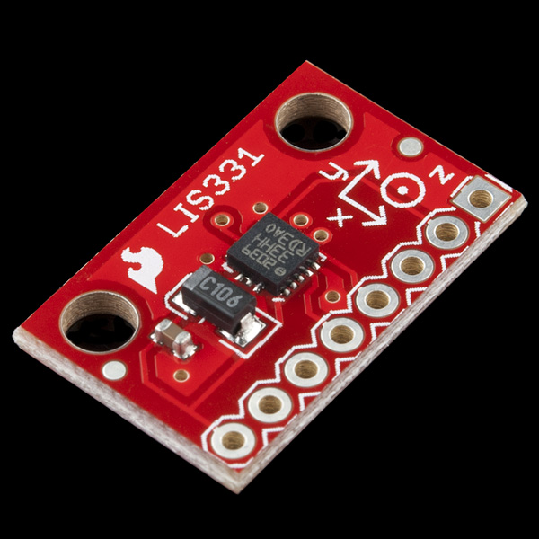
This is a breakout board for the ultra low-power LIS331HH three axis linear accelerometer. The device has a digital I2C/SPI serial interface which makes it ideal for using in embedded applications. All major pins are broken out to 0.1" spaced headers. It also includes two mounting holes as well.
The LIS331HH from STMicroelectronics is an ultra low-power full-scale three axis MEMS linear accelerometer. It has a digital I2C/SPI serial interface which makes it ideal for using in embedded applications. The device also features ultra low-power operational modes that allow advanced power saving and smart sleep to wake-up functions.
The LIS331HH has dynamically user selectable full scales of +-6g/+-12g/+-24g and is capable of measuring accelerations with output data rates from 0.5 Hz to 1kHz. The self-test capability allows the user to check the functioning of the sensor in the final application.
Not sure which accelerometer is right for you? Our Accelerometer and Gyro Buying Guide might help!
- 2.16-3.6V input
- Ultra low-current mode, down to 10uA
- 6g/12g/24g selectable
- I2C/SPI digital output
- 16 bit data output
- Schematic
- Eagle Files
- Raspberry Pi Zero Helmet Impact Force Monitor (Python)
- Datasheet (LIS331HH)
- GitHub (Design Files & Example Code)
SparkFun Triple Axis Accelerometer Breakout - LIS331 Product Help and Resources
Raspberry Pi Zero Helmet Impact Force Monitor
March 8, 2018
How much impact can the human body handle? This tutorial will teach you how to build your very own impact force monitor using a helmet, Raspberry Pi Zero, and accelerometer!
Resources and Going Further
For those looking for an Arduino Library, check out David Irvine LIS331 Arduino library:
Documentation - Irvine's blog post about the Arduino LIS331 Library Overview
We also released a Arduino library for the H3LIS331DL which is compatible with the LIS331 family of accelerometers that might be of some use:
Core Skill: Soldering
This skill defines how difficult the soldering is on a particular product. It might be a couple simple solder joints, or require special reflow tools.
Skill Level: Noob - Some basic soldering is required, but it is limited to a just a few pins, basic through-hole soldering, and couple (if any) polarized components. A basic soldering iron is all you should need.
See all skill levels
Core Skill: Programming
If a board needs code or communicates somehow, you're going to need to know how to program or interface with it. The programming skill is all about communication and code.
Skill Level: Competent - The toolchain for programming is a bit more complex and will examples may not be explicitly provided for you. You will be required to have a fundamental knowledge of programming and be required to provide your own code. You may need to modify existing libraries or code to work with your specific hardware. Sensor and hardware interfaces will be SPI or I2C.
See all skill levels
Core Skill: Electrical Prototyping
If it requires power, you need to know how much, what all the pins do, and how to hook it up. You may need to reference datasheets, schematics, and know the ins and outs of electronics.
Skill Level: Rookie - You may be required to know a bit more about the component, such as orientation, or how to hook it up, in addition to power requirements. You will need to understand polarized components.
See all skill levels
Comments
Looking for answers to technical questions?
We welcome your comments and suggestions below. However, if you are looking for solutions to technical questions please see our Technical Assistance page.
Customer Reviews
4.7 out of 5
Based on 3 ratings:
2 of 2 found this helpful:
Model rocket acceleration
I'll be ordering a bunch more of these for my freshman community-college course in microcontroller-based instrumentation systems. We'll send them up in model rockets ("E" motors) with an Arduino Feather datalogger and a temperature/pressure (thus altitude) sensor. I chose this LIS331 accelerometer because of its 24g range. I hacked the driver to work with I2C, and find I can take 3-axis acceleration data and temp/pressure data at a rate of at least 100 datapoints per second, and write them to SD. Thanks for making this unit available!
Delivers as advertised!
Reliable, robust device. External axes marking seems to be inconsistent with actual MEMS axes. A FIFO buffer would be useful.
What is the maximum sampling frequency for this accelerometer?
Check the data sheet above in the 'documents' section for this information. If you have any other technical questions, please see our Technical Assistance page.
I bought this product. Connected via I2C interface. The output values of the individual axes are in large dispersion. The datasheet says something about calibration. For more accurate measurements. I just didn't understand the calibration.
Thank you for your response
You can find a new and much more complete Arduino LIS331 library here: https://github.com/szotsaki/LIS331. It also can be found in the Arduino IDE library browser.
Please, report bugs and possible improvements :). Thank you!
We have bought several Sparfkun Accelerometer Breakout boards. Two are currently attached to a Teensy 3.2 USB development board who samples at 1000 Hz. We notice that the accelerometer values sometimes don't vary every millisecond.
Is it possible that the accelerometers do not reach the 1000 Hz as stated in the product sheet??
we are trying to interface LIS331HH with MSP430 MCU but we are getting the same value on MISO pin which we are sending on MOSI pin of Accelerometer , just like we are getting a echo output from input.. please help me to sort out this.
This question references the LIS331 Data Sheet:
Table 4 (p10) Table 19 (p25)
Does anyone know why the low pass frequencies given in table 19 are more half of the out put data rates (ODRs), even though the band widths are cited in table 4 are half of the ODRs? Normally you wouldn't want the data reaching the sampler to have any frequencies over half the ODR removed so that they don't create aliases in the sampled data.
Has anyone got this sensor to work on the PSOC3 or 4. I have been trying for weeks and can't seam to be getting to work. I am trying to run it off 4 wire SPI.
Hello, I am using this accelerometer through SPI. I can read data but I think something is not very good. When I set register 0x20 to 0x37 and then read it, it returns 0x3F (instead of 0x37). Does anybody know why that is happening?
I am putting this and an altitude sensor on a model rocket with a data logger. I can't wait!
This is definitely got the range +-6g/+-12g/+-24g right?
My unit seems to cap at +-2g if i set register to lowest range and +-8 at highest.
I assume I have scaled in the code correctly because I see a total of 1g when the unit has axis orientated inline with gravity.
Anybody else seen this?
I bought this product months ago, it works fine.
did you check the lis331 chip on PCB? is it marked as "lis331hh" or something else like "lis331dlh" or 'lis331dh'?
if it is lis331hh, it is definitely got the range +-6g/+-12g/+-24g! if no, there must be something wrong.
Quick "Hidden Gem" from the Data Sheet - Unlike many I2C devices, doing a multiple-byte read (e.g. to read all x,y,z values) does not automatically advance the register pointer, unless you set bit 7 in the register address. Reading 6 values from register 0x28 returns you the low order x-acceleration byte 6 times - reading 6 values from register 0xA8 will return the 3 axis 16 bit acceleration values.
are you sure this thing gives 16-bit data output? From the resolution in the datasheet, it looks like it's 12-bits not 16... Can someone double-check this please?
The data output is 16 bits but right 4 bits are '0000' which is not mentioned in datasheet I think(at least I have not found and I figured out by checking the data output). hope this help.^_^
I have been looking to use this board and compile the code.
The sample code talks about using arduino but the code isn't for the arduino IDE and I don't know what was used to compile it.
Any chance of getting code that works as demo code for the arduino IDE ?
This device is pretty useless to me atm.
Nice accelerometer, but just in case no one's noticed, the pin labels (back side) are the wrong direction. Not a big deal, but if you're taking the time to label them, label them correctly.
OK. My brilliant plan -- output from LIS331 (in SPI mode) to data in (DIN) on an XBee for remote accelerometer (talking to an XBee on an XBee Dongle).
Problem: the 331 needs a clock circuit (for either SPI or I2C). Suggestions needed ASAP. I don't think a 555 timer will work, but if it will, can someone give me the C/R1/R2 values if I want 9600 baud SPI output?
Thanks in advance.
Nevermind, these two pages helped:
http://www.eleinmec.com/article.asp?3
http://www.csgnetwork.com/ne555timer2calc.html
Off to RadioShack (sorry!) for a 555 and some resistors...
The example code uses the SPI interface, I wrote an I2C implementation here:
http://code.google.com/p/loguino/source/browse/#svn%2Ftrunk%2Flibraries%2FLIS331
when using i2C to write and read the registers of this accer, all the data I read from all registers is 0x31. I already send data 0x37 to register 0x20. Reading the register 0x20 turns out 0x31 and so the other registers. Could anyone help?
Why it Accelerometer module in "Breakout Boards"?
It's not anymore.