- Home
- Ultrasonic Range Finder - LV-MaxSonar-EZ1 (Retail)


Ultrasonic Range Finder - LV-MaxSonar-EZ1 (Retail)
This is the same product as the Maxbotix LV-EZ1. The difference is this version comes in fancy clamshell packaging meant for our distributors that need it. Regular customers are welcome to order, but we want to limit the amount of extra packaging finding its way into the trash heap.
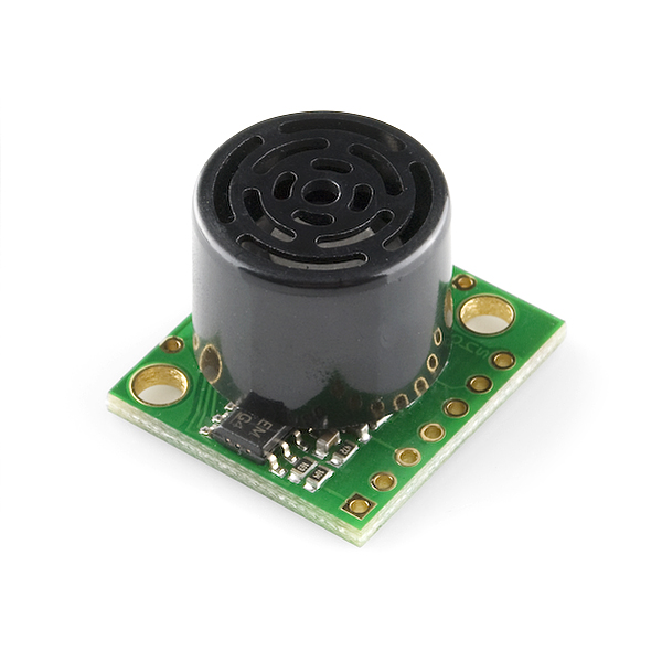
This is the fantastically easy to use sensor from Maxbotix. We are extremely pleased with the size, quality, and ease of use of this little range finder. The serial interface is a bit odd (it's RS232 instead of standard TTL), but the PWM and Analog interfaces will allow any micro to listen easily enough. The sensor provides very accurate readings of 0 to 255 inches (0 to 6.45m) in 1 inch increments with little or no dead zone!
Maxbotix is offering the EZ0, EZ1, EZ2, EZ3, and EZ4 with progressively narrower beam angles allowing the sensor to match the application. Please see beam width explanation below.
Control up to 10 sensors with only two pins! Checkout the Maxbotix FAQ listed below.
- 42kHz Ultrasonic sensor
- Operates from 2.5-5.5V
- Low 2mA supply current
- 20Hz reading rate
- RS232 Serial Output - 9600bps
- Analog Output - 10mV/inch
- PWM Output - 147uS/inch
- Small, light weight module
- Beam Width Explanation
- LV-EZ1 Datasheet
- Maxbotix FAQ
- Sensor Selection Guide
-
Checkout Mikey Sklar's flame-based trampoline, the high-lighter, using the EZ1!
Ultrasonic Range Finder - LV-MaxSonar-EZ1 (Retail) Product Help and Resources
"RS232" Output or Inverted TTL
If the ultrasonic range finder indicates that it has an "RS232 Serial Output" and is outputting an inverting signal with the voltage level based on Vcc, you could just use an inverting circuit using a transistor to invert the signal. This is not a standard RS232 that uses +/-12V. There are a few methods of flipping this signal through hardware or software. The resources and going further will provide specific examples.
Inverting Signal w/ Hardware
Doing a quick test using a retired NPN transistor from our storefront, I was able to get it working based on the circuit using a RedBoard Programmed with Arduino. I was using an Arduino so Vcc in my circuit was 5V. Since it's basically two diodes within the transistor, you will want to use resistors to limit the current. I just used two 330Ohm resistors just like I was turning on an LED. You probably do not need to do this but the values might need to be adjusted when using it at higher speeds or if the transistor is not fully turning ON/OFF. Testing with a multimeter, it worked as expected. An input of 5V would result in 0V (logic LOW) on the output since the transistor was turning on. With an input of 0V, the transistor would not be conducting so the output would be held HIGH at 5V. Using an Arduino serial passthrough for further testing, I was able to view the ultrasonic sensor's output data without any problems.
"RS232" Output and Inverting w/ Software
Otherwise, you could be clever in writing your code to store the value and possibly apply some sort of logical NOT operation. In Arduino, there is a special feature using software serial that inverts the signal by setting a parameter to true [ "Software Serial Constructor" – https://www.arduino.cc/en/Reference/SoftwareSerialConstructor ]. There was someone in the Arduino forums that provided example code to invert the output, parse the data, and output it through the serial monitor here => [ User "Goldthing" - http://forum.arduino.cc/index.php?topic=114808.msg864009#msg864009 ].
Connecting Ultrasonic Sensor to Raspberry Pi
There is a tutorial from MaxBotix that shows you how to connect ultrasonic sensors to Raspberry Pis => [ http://www.maxbotix.com/Raspberry-Pi-with-Ultrasonic-Sensors-144/ ]. Certain ultrasonic sensors listed in the article require an inverter. If the ultrasonic range finder's output serial output is " RS232 " like the sensors listed under "Ultrasonic Sensors that Require an Inverter" , this indicates that the signal is basically an inverted output with the voltage level based on Vcc.
Therefore, you would need to follow the tutorial and use a serial inverter in order to use it with the Raspberry Pi. If you are using a Raspberry Pi a transistor, Vcc should be 3.3V since the Pi uses a 3.3V system.
Resources and Going Further
Core Skill: Soldering
This skill defines how difficult the soldering is on a particular product. It might be a couple simple solder joints, or require special reflow tools.
Skill Level: Noob - Some basic soldering is required, but it is limited to a just a few pins, basic through-hole soldering, and couple (if any) polarized components. A basic soldering iron is all you should need.
See all skill levels
Core Skill: Programming
If a board needs code or communicates somehow, you're going to need to know how to program or interface with it. The programming skill is all about communication and code.
Skill Level: Rookie - You will need a better fundamental understand of what code is, and how it works. You will be using beginner-level software and development tools like Arduino. You will be dealing directly with code, but numerous examples and libraries are available. Sensors or shields will communicate with serial or TTL.
See all skill levels
Core Skill: Electrical Prototyping
If it requires power, you need to know how much, what all the pins do, and how to hook it up. You may need to reference datasheets, schematics, and know the ins and outs of electronics.
Skill Level: Noob - You don't need to reference a datasheet, but you will need to know basic power requirements.
See all skill levels
Comments
Looking for answers to technical questions?
We welcome your comments and suggestions below. However, if you are looking for solutions to technical questions please see our Technical Assistance page.
Customer Reviews
No reviews yet.
How sensitive is this sensor? I need it to be capable of receiving input data from a distance of at least 10 ft away.
Will people stop watching their favorite tv shows, movies (porn) because someone has on a cross necklace, or cross tattoo etc. Most people don't even notice it, as long as it has what they want, they don't care what's in the background. There are soo many more important things to worry about like finding a cure for cancer, or cure stupidity. :-)
RobertC, do you have the ability to disable comments for certain products?
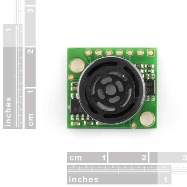
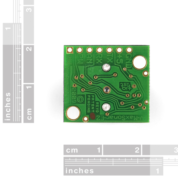
Perhaps the picture of the back side of the board should be removed as well.
Why, that's what it looks like. It has a cross and a fish thing. I hear these shapes, in this particular arrangement, carry a religious connotation.
Yes, but some people are easily-insulted. Removing the picture may result in more sales for this board.
Yes.
Those using this product should be aware that Maxbotix has seen fit to embellish their circuit traces with pro-Christian symbols (visible on the last picture, upside down). Personally, I think it's totally unethical to force customers to act as unknowing bearers of religious propaganda in this form or any other. We, as engineers and scientists, fight a daily battle against ignorance and prejudice, most of which can trace its roots back to religion and political ideology. We should demand therefore, that the products we use be 100% dogma-free. A circuit board is no place for this type of religious mischief, not now, not ever. Part of having freedom OF religion is having freedom FROM religion.
Rich, you must have a guilty conscience and too much spare time. Thanks to the constitution making it clear that we were endowed by our Creator (Yes, TJ used a Capitol C), with certain unalienable rights, Maxbotix is free to design their boards however the hell they want and you are free to not purchase them because of it. Dogma is present from all angles. Please don't foist your own arrogant dogma on the rest if us.
Sparkfun posted a picture of this board's reverse side. They aren't trying to stow the symbol away on the board.
No more religious comments regarding this product please. It's been discussed, you aren't bringing up anything new, it's all been said before.
He's right, the traces on the back of the board look eerily similar to a Flying Spaghetti Monster.