- Home
- Product Categories
- RF
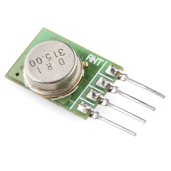
- RF Link Transmitter - 315MHz

These wireless transmitters work with our 315MHz receivers. They can easily fit into a breadboard and work well with microcontrollers to create a very simple wireless data link. Since these are only transmitters, they will only work communicating data one-way, you would need two pairs (of different frequencies) to act as a transmitter/receiver pair.
Note: These modules are indiscriminate and will receive a fair amount of noise. Both the transmitter and receiver work at common frequencies and don't have IDs. Therefore, a method of filtering this noise and pairing transmitter and receiver will be necessary. The example code below shows such an example for basic operation. Please refer to the example code and links below for ways to accomplish a robust wireless data link.
- 315MHz
- 500ft range (given perfect conditions)
- 4800bps data rate
- 5V supply voltage
RF Link Transmitter - 315MHz Product Help and Resources
1 of 2 found this helpful:
Testing the RF Link transmitter
To ensure that the RF links are working, we recommend trying to get the RF links working with our example code first. However, I have tested the RF modules with the VirtualWire librarie and Arduino 1.0.6 IDE software. I was able to get it working with this library => VirtualWire 1.20. This library worked with both Arduino 0023 and Arduino 1.0.6.
RF Links
The example code used with the an Arduino microcontroller explains the setup for each RF Link. This is the setup which will work with either RF Link frequency band.
Transmitter Code (4 pin module)
Pin 3 of your Arduino should connect to pin 2 of your RF Link Transmitter 315MHz. Button is connected to the transmitting Arduino on pin 8 separate from the RF Link Transmitter. When a button is pressed on the transmitter, the corresponding LED should light up on the receiver and a character will be sent.
Receiver Code (8 pin module)
Pin 2 of your Arduino should connect to pin 2 of your RF Link Receiver 315MHz. When the button is pressed from the transmitter side, the corresponding LED on this side will light up on pin 8. One thing to note is that the associated LED will not light up on the receiver end if you do not have the associated character to check if it is what is received. An example is if you send a string of characters “Pin 4,” the receiver LED will not light up when the characters “Pin ” is sent. It will only light up when it sees the number “4”.
Note 1: It seems like when the receiver code is compiled with Arduino 0023 that the characters sent show a character and a space right after it in the serial monitor. When compiled with Arduino 1.0.6, you get an hex value and a space that is related to the ASCII character that was sent. You can verify it by checking the ASCII table and it will show that the hexadecimal value that was sent is indeed the character that was sent from the receiver. This has something to do with the shift in versions from Arduino’s 0023 to the Arduino 1.0 and above. Something was modified in the compiler or how a function was defined in the Arduino IDE.
Note 2: The RF Links are cheap wireless modules so you might get some intermittent data transmission/ corrupt data after a certain distance. They have a lot of noise. A better and more secure option might be to use the XBee Series 1 Wireless Modules.
Note 3: I am aware that the Virtual Library is EOL and that the RadioHead library supersedes it. I found out in the middle of updating the code. You shouldn’t have a problem with the library though even though it is EOL.
Core Skill: Programming
If a board needs code or communicates somehow, you're going to need to know how to program or interface with it. The programming skill is all about communication and code.
Skill Level: Rookie - You will need a better fundamental understand of what code is, and how it works. You will be using beginner-level software and development tools like Arduino. You will be dealing directly with code, but numerous examples and libraries are available. Sensors or shields will communicate with serial or TTL.
See all skill levels
Core Skill: Electrical Prototyping
If it requires power, you need to know how much, what all the pins do, and how to hook it up. You may need to reference datasheets, schematics, and know the ins and outs of electronics.
Skill Level: Rookie - You may be required to know a bit more about the component, such as orientation, or how to hook it up, in addition to power requirements. You will need to understand polarized components.
See all skill levels
Comments
Looking for answers to technical questions?
We welcome your comments and suggestions below. However, if you are looking for solutions to technical questions please see our Technical Assistance page.
Customer Reviews
2 out of 5
Based on 2 ratings:
1 of 1 found this helpful:
Cool device but needs better example code
I"m a 31 year old EE student with clinically diagnosed ADD. This product was purchased to build an RF sniffer (see following link).
( https://z4ziggy.wordpress.com/2014/06/27/rf-sniffer-open-gates-cars-and-rf-remote-controlled-devices-with-ease/).
I did, like other users, have a difficult time understanding how to hook this device up and determine whether or not it was working. I"m sure for more experienced users it wasn't too difficult, but for me it was.
I would suggest a systematic approach ( step 1 do this, step 2 do that, open serial monitor and expect to see something like this....) for initial link setup. The documentation on the product's website helped but it was really the following website that allowed me to get up and running.
(http://arduinobasics.blogspot.com/2014/06/433-mhz-rf-module-with-arduino-tutorial.html)
The KLP Tutorial mentions signal conditioning and filtering to improve signal TX and RX but doesn't reference or provide outside tech sheets or examples (LPF, HPF, threshold detector/limiter circuitry) . I would have liked to have been provided with a link or appendix with an example of how to do that.
All said and done, the overall process to get my RF link up and running allowed me to learn a lot about ASK and signal conditioning. I guess that's the point of giving just enough information- to invoke learning. However, for those like myself who have a deep passion for EE but struggle to learn in a timely manner, the above suggestions would not only invoke learning but keep me coming back knowing that SparkFun is truly a one stop shop for any project.
Poorly documented and fails to work out of the box
This was purchased as a pair: the RF Link Transmitter - 315MHz and RF Link Receiver - 4800bps (315MHz). When placed on two boards, and gave ground to the GND pins, 5V to the VCC pins, and data on the transmitter pins, I was unable to find out which pin on the receiver to use to read in via my Arduino. I followed several tutorials but none of them had the same transmitter or receiver as this. It was labelled as the same, but the pictures in the video didn't match. Nor did the pinouts. So who knows. However, I tried both pins on the receiver. When giving 5V to the transmitter data pin, nothing changed from what came out of the data pins of the receiver. I then tried soldering on 13cm wires to the antenna pins, per several sites, coiling the antenna on the receiver and keeping it straight on the transmitter. Still no change. All I read was 1.32V on the receiver whether the transmitter had 5V on it's data or 0V. The datasheets offered no help. I wanted to try VirtualWire, but if the primary analog voltage functions did nothing, VirtualWire wouldn't even be worth a test. However, I did try it, just in case. No surprise, it didn't work either.
So, in short, I understand the transmitter and receiver is only a $7 purchase, plus shipping when put together, but I would at least expect them to work somewhat, rather than not at all. It is a waste of time. Buy more expensive ones elsewhere that has solid documentation.
Sorry to hear that neither this nor the receiver seem to be working for you. I would suggest getting in touch with our tech support team, they should be able to help you resolve these issues.
The Features has a 5V supply comment but can the unit still tolerate 12VDC?
Does anyone know if this TX can be used to send commands to an X-10 transceiver like the TM571? Most X10 links I see say 310MHz rather than 315 but I don't know if they are just being approximate! TIA
Be careful using the 315 Mhz transmitter near a GPS receiver, The fifth harmonic of 315 MHz is 1575 MHz. 1575 MHz is the GPS carrier frequency. Depending upon your GPS receiver, you can get GPS receiver desensitization or total jamming of the GPS signal.
For GPS applications, the 434 MHz link is a better choice. For bi-directional links have the GPS send on 434 Mhz and receive on 315 MHz. This get the potentially interfering 315 MHz signal further from the GPS.
For more tutorials on the RF link modules:
http://www.glacialwanderer.com/hobbyrobotics/?p=291
http://letsmakerobots.com/node/12336
http://winavr.scienceprog.com/example-avr-projects/running-tx433-and-rx433-rf-modules-with-avr-microcontrollers.html
http://narobo.com/articles/rfmodules.html
Could I send a one-bit (on/off) signal without encoding, virtualWire? Basically, without a uC. I just want an LED to turn on connected to the receiver when a button is pressed on the transmitter. Is this possible?
Do you have to use tx and rx pins with these radio transmitters/receivers? I ask because I just bought the ATTiny85 and would like to be able to use this as the receiver and possibly another to transmit. I have know idea if this is possible or not with the ATTiny85 so any help is greatly appreciated.
So would the antenna just be a long wire that you attach to the pins? Does it have to be any specific metal or size?
You have a few options. Check the KLP walk through linked above for tips and considerations on signal strength.
Thanks for the reply. I may just stick to a wire but the actual antennas are certainly worth keeping in mind if distance becomes a problem!
What about this transmitter limits its data rate to 8KBpS? Is it something about the circuit, or a limit imposed to keep it legal? Unless something in the internal circuits limits to that data rate, the actual capability is possibly a lot higher, considering the xmit frequency.
Anyone know where to find the 303.825MHz version of this part? The mfgr seems to make one, but nobody carries it.
Really dumb question: can you have on receiver and multiple senders? Or do they each need to be paired on different frequencies?
I just spent all night working on mine. Turns out, these things really love a 330uF cap from ground to vcc
These transmitters are awesome! I am using one to control off the shelf wireless outlet switches that are available for dirt cheap during the holiday season. I used the corresponding 315MHz receiver and my Rigol DS1052E scope to decode the protocol from the remotes and reimplemented it on an ATTiny2313 microcontroller. I'm using a capacitor charge pump driven by a microcontroller PWM pin to boost the 5V USB voltage powering my board to 8-9V DC for the transmitter. It can take up to 12V and the higher voltage means longer range. This setup easily covers my whole house even though the transmitter is located in the front corner room. I can control 12 outlets (lamps, fans, Christmas lights, whatever) from anywhere using my phone. Thanks 315MHz transmitter, you're awesome! The total board (USB serial, ATTiny2313, transmitter, homemade PCB, etc) cost around $10 total and the outlets are $15 for 3.
I was about to do exactly the same thing. Don't suppose you can share what you found out about the protocol to save me the trouble of working it out too? Thanks.
Is there a difference between the 315MHz and 434MHz versions of this? (Not in the physical product, but in the range, quality, etc.)
I would like to see the example circuit you were able to get the 500ft range. I am interested in knowing the antenna configuration + groundplane. Were you able to use something like ANT-315-HETH from Linx technologies?
Also - Supply Voltage - I have seen some of these have a range between 3-12v. Is the 5v the maximum? The data sheet says 1.5 ~12V. Do you have estimates of range based on voltage. Trying to go 100m.
http://www.youtube.com/watch?v=wlpXzF0Gv4U&list=PLADOxch6A_u-stWlF93snAUoYDmZ5_6Tg&index=1
Wireless communication between a PC and quadcopter using this RF transmitter, receiver...
I used this and the accompanying receiver in an (Arduino) tutorial. Link. I also used your code in the tutorial, hope you don't mind. (Code was accredited to Sparkfun, the header was left at the top)
The Features here list 5V supply voltage but the datasheet supply voltage 1.5-12 and an operating voltage of 3-12.
So can this be used with 3.3V circuitry?
If I used this transmitter as a simple on/off sort of beeper, could I get more than 500 feet of range? I want to use it as an RF beacon, and put it on a remote control plane so I can home in on the signal with the receiver that goes with this. Also I can't send audio tones over this, right?
I wonder if you could put a transistor on the antena line to get more power or paralell 2 of them to get double the output power...
I am using one of these and companion receiver with RC chips TX-2B, RX-2B for simple on premise remote control: they work great. No issues with decoding errors. I power up the transmitter only when new data is ready to reduce potential interference. Using well bypassed power supply lines (10uF tantalum in parallel with two .1 uF). Looking forward to my next application.
How does this work? You apply power and then it transmits a signal?
Is the Arduino Library and Example Code outdated for this? When trying it all I get is a bunch of compile errors (using Arduino IDE 1.0.1) for VirtualWire.h and then it saying one of the vw_ functions isn't declared. Kind of annoying to have libraries and example code that doesn't work :(
In answer to my own question yep, Sparkfun needs to update their Library links.
v1.9 works here: http://www.open.com.au/mikem/arduino/
http://mbed.org/users/4180_1/notebook/ir-and-rf-remote-controls/ has a code example for mbed sending characters to the matching receiver
Anyone know the best antenna shape for best range?
I'm trying to rig up a detector to tell when the mailman has dropped off the mail, but so far the receiver starts failing just ~5' from the mailbox.
So far I have a 5/8 wavelength antenna, completely coiled. The whole thing is powered on 12V, which is the rated maximum of the transmitter.
Is straight better than coiled?
Im not sure, maybe put a wire along the post?(or coil it around the post.) I might get one, seeing as they're online 3.50
You get what you pay for holds true for this little gem. Thinking that an xbee would be overkill to transmit a 4 byte message, I decided to try this product. I purchased one of each flavor. Both 315 and 433 Mhz radios produce nothing more than a continous stream of noise that no amount of software, checksums and programming can reliably filter out. I am lucky to get 1 good 4 byte message out of 20 transmits.
I have to admit, I damn nearly pulled out my hair using these 315 MHz TX and RX modules. BUT I finally got them to work and consistently at 2400Bps. The trick to make them work for me was to add filtering caps (330uF or larger) to the power lines feeding the modules. The second thing is the antennas, during testing at close range (5-12 inches), the antenna on the RX had to be removed, I don't know why, but if I didn't it caused nothing but a constant stream of garbage. The antennas also needed to be ~9 inches in length and straight. After this, I can transmit the string '|T:264|H:500|C:764;' (Temp 26.4C, Humidity 50% and checksum temp+humid read from DHT22) every 10 seconds with little failure attempts.
Reading this and other comments, I have the following suggestions. 1) have clean, stable power going to the Tx and Rx units. These have gain and mixer stages that will pick up and amplify pretty much everything. Put a scope on the rails and make sure they are steady when the Tx/Rx units are operating. 2) Put a low-pass filter on the Tx output. It doesn't have to be really steep and can have a passband >= 330 MHz. That will make sure that the harmonics mentioned above don't interfere with other devices. Of course, a bandpass filter would be better, and is only slightly more complicated. If someone can determine the output impedance of the Tx antenna port, then try to match that. 3) The wavelength of a 315 MHz transmitter is about 95 cm. You should get decent efficiency with a 1/4 wavelength = 23.8 cm wire antenna provided it's isolated from other conductors. Check out ARRL info on antennas for other kinds that may be useful... 4) If you are lucky enough to have a spectrum analyzer, use it to see what's going on with the Tx. Pay attention to "spurs" outside the desired band and the above-mentioned harmonics. If you only have an oscilloscope, you may still be in luck if it's digital storage and has an FFT mode. You can single-shot trigger and take a look at the spectrum using the FFT (of course, the scope has to be 350 MHz or better (probably 500 MHz)...
Have fun,
I will try the filtering caps, and report back how it worked for me. I'm hoping this will make it work better!
I'm having trouble with this product. I have two arduinos one transmitting and one receiving and I'm confident they are wired correctly. None of the hello worlds are working. I can plug a wire from the antenna of the sender to the antenna of the receiver and the data goes through, but wirelessly is still a mystery. Is there a simple way to diagnose if I have a bad transmitter or receiver?
What code are you using?
other TWS-BS modules? Sparkfun sells the 3 (433.92) and this one, the 6. I'm looking for a TWS-BS-5 (318) and I am unable to find a source. Anyone here got some ideas?
As an example of what you can do with these, we created a TPMS/key fob spoofer with the older version of this and an FTDI chip. Significantly cheaper than the USRP some people were using, but the signal was much noisier.
http://mbed.org/users/lotfi_baghli/notebook/x10-server/ has a code example using this device with the mbed processor module to send wireless commands to control X10 home automation modules.
How much does it weigh?
So, is this just an improved version of WRL-08945?
It seems to have about the same specs (315MHz, 500ft, 4800bps) at twice the price.
Also, the spec sheet doesn't indicate what to use for an antenna. I assume it would use a 23cm wire like the WRL-08945 modules do.
I did the math and came up with 17.8in for a straight wire antenna. I tried it and it seemed to make a big diference at 2400 baud.
a length of wire is fine.
it's the same as the other. I lowered the price on 8945 since it's an old supplier and we can't get them anymore. they retailed for the same as these. snatch up the others cheap while we still have them.
Guaranteed the old batch of transmitters (WRL-08945) work fine with the new batch of receivers (WRL-10533)?
I bought a WRL-08945 transmitter and a WRL-10533 receiver, and I can tell you that they work together.
Just make sure to use an external antenna, unless you want to get a 2 centimeters range.