- Home
- Product Categories
- Sensors
- Serial Accelerometer Dongle

Serial Accelerometer Dongle
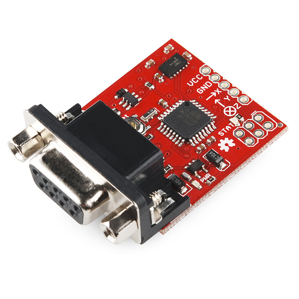
The Serial Accelerometer Dongle is a 3 axis accelerometer up to +/-6g with a simple serial interface. The Serial Accelerometer Dongle has a variable baud rate, a factory reset command, and a complete triple axis measurement system based on the MMA7361 MEMS motion sensor from Freescale. Power is gained from any RS232 port (including USB-to-RS232 converters) so no external power supply is needed. The new version replaces the onboard PIC with an ATMega328 . The board has software configurable settings to select between 2 different sensing ranges (+/- 1.5 and 6g).
The board outputs real-time accelerations from 9600 to 57600bps using visible ASCII characters. It is compatible with any RS232 Comm port in conjunction with any terminal program (Hyperterminal, VB Programs, or anything else that can read the comm port). It works fine with USB-RS232 converters.
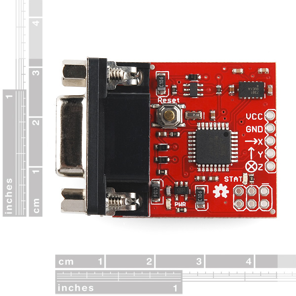
- 1.3 x 1.25" (33.2 x 31.7 mm)
Serial Accelerometer Dongle Product Help and Resources
Core Skill: Soldering
This skill defines how difficult the soldering is on a particular product. It might be a couple simple solder joints, or require special reflow tools.
Skill Level: Noob - Some basic soldering is required, but it is limited to a just a few pins, basic through-hole soldering, and couple (if any) polarized components. A basic soldering iron is all you should need.
See all skill levels
Core Skill: Programming
If a board needs code or communicates somehow, you're going to need to know how to program or interface with it. The programming skill is all about communication and code.
Skill Level: Rookie - You will need a better fundamental understand of what code is, and how it works. You will be using beginner-level software and development tools like Arduino. You will be dealing directly with code, but numerous examples and libraries are available. Sensors or shields will communicate with serial or TTL.
See all skill levels
Core Skill: Electrical Prototyping
If it requires power, you need to know how much, what all the pins do, and how to hook it up. You may need to reference datasheets, schematics, and know the ins and outs of electronics.
Skill Level: Noob - You don't need to reference a datasheet, but you will need to know basic power requirements.
See all skill levels
Comments
Looking for answers to technical questions?
We welcome your comments and suggestions below. However, if you are looking for solutions to technical questions please see our Technical Assistance page.
Customer Reviews
No reviews yet.
I have forked the original code repo and made the changes as per trevorshannons suggestions. Still in the process of testing to see if the problem is fully resolved. Feel free to improve things further.
https://github.com/archfiend/Serial-Accelerometer-Dongle
Would there be any reason why I wouldn't be able to send the data through a blue tooth module?
Hello,i bought the accelerometer few days ago.My controller has UARTS (only with rx tx and gnd connectios).So i externally applied vcc and gnd.The accelerometer got powered ON still am not able to receive any data on UART.Can someone help me please?
hello , i bought the accelerometer few days ago , but i tried to get the information on hyperterminal but it doesnt work . it gives me (ySN)ëÒÛSÂ) the accelerometer takes power from the serial port as they sad before . can someone help me please ?
Double check your connections are all good and power is appropriate. The data you are getting out may be due to a baud rate mismatch. I would double check that, and if you are still having issues after that, please contact tech support.
Uld you specify software that would record data for 24h I need to report inteligible data to a courtCo
It depends on whether you're using an external data storage device or internal on your computer. It also is dependent on what other supplies are involved in your project. Again, techsupport@sparkfun can help you out further with more detailed specifics for your project.
i didn't see enough noise to make this 'unusable' but i did see some strange jumps every once in a while. for example, for one sample, x would increase a lot while z would simultaneously decrease a lot. suspicious...
taking into account what others have already mentioned, i made the following change to the firmware (sorry for pseudo code) and i seem to have eliminated those random jumps.
I managed to do something similar to this, but I don't understand why the ADCL and ADCH are stored in a temporary variable in the "else" block. Are you using that temporary variable somewhere in the code? Shouldn't the values be discarded? That's what I did and the strange jumps are gone.
trevorshannon,
Thank you, you are my hero! After "making do" (via very heavy filtering) with three of these noisy accelometers last year (4/2012) for a STEM activity, I took a chance and bought 4 more this year (4/2013). The new ones were STILL just as noisy. (They are more notably noisy at 100Hz, btw.) But, with the four new ones I was able to re-program them as per your directions and suggestions, and now they work perfectly!
As a note of general interest, however, I think there is some difference between the 2012 batch and the 2013 batch... I could successfully re-program the 2013 batch using your directions, but trying to re-program the 2012 batch in the exact same way yielded an "avrdude: stk500_getsync()" error. (The AtMega328P on the 2012 batch was labeled "AU 1110", whereas the chip on the 2013 batch was labeled "AU 1224".)
Thanks again!
(And hopefully SparkFun will someday start shipping this product with patched firmware!)
I'm also having noise issues with this device, but I don't have the necessary expertise to modify the firmware code based on trevorshannon's pseudocode. Would you mind sharing your solution? Perhaps fork the github repository?
An update on where I am with respect to the glitch affecting the ADC output. I haven't been successful in updating the firmware, I get an error from adrdude "avrdude: stk500_getsync(): not in sync: resp=0x1c" (with a different resp= number depending on the baud rate). This seems to be a common problem, but I haven't been able to find a fix. I'm not sure if http://www.arduino.cc/playground/Code/MegaISP is relevant at all - I did try patching avrdude with a delay and various combinations with pressing the reset button, but no success. I'm not going to try fiddling with the reset lines on the dongle unless I get positive confirmation that this would fix my problem. I've ordered a pocket AVR programmer so I'll see if I can use that instead.
On the firmware bug, if I understand Etienne and the datasheets properly, the problem is that in free-running mode the ADC conversions occur at quite rapid intervals and it is possible that an ADC conversion can happen while ADC_vect is still executing, before the ADC channel is updated. Therefore, as soon as ADC_vect reenables interrupts it gets called again but with the ADC reading from the wrong channel. In the datasheet for the ADC at http://www.atmel.com/Images/doc8444.pdf there is a note "It is recommended to discard the first conversion result (like whenever there is a change in ADC configuration like voltage reference / ADC channel change)", which suggests that when the channel is changed we should discard the next reading from the ADC anyway. I've modified the firmware to do this, but I can't try it out until I can find a way of loading the firmware.
Also, looking at the firmware I am not sure if there is another problem: when calculating the average values in the sensorADCCount variable, free-running mode is disabled but as far as I can tell this doesn't disable interrupts (contrary to the comment in the code?), so is it possible that there is one more interrupt still pending when it enters the loop? This might be harmless, if the update to adcReading is atomic(?). But I'm curious as to why the change to the free-running mode, rather than simply disabling interrupts while calculating the sensorADCCount.
for what it's worth, here is how i programmed this module using winAVR.
install winAVR
in the source code directory on github, edit the Makefile. I was programming via the built-in serial port, so the options of interest are under Programming Options (avrdude serial bootloader) [line 336] You need to change SERIAL_AVRDUDE and SERIAL_AVRDUDE_CONFIG to match your arduino install directory. no spaces allowed in the path!. You also need to change SERIAL_AVRDUDE_PORT to match the port you are using (it was COM1 for me). Finally, change SERIAL_AVRDUDE_PROGRAMMER from stk500v1 to arduino.
open a command line and navigate to the accelerometer dongle source directory.
that's it!
Hi ryowen84,
The ADC_vect routine in the firmware code has a minor glitch with very visible consequences Glitch: When the ADC finishes reading a value (on channel X for example), and ADC_vect is already executing (for a previous reading on the same channel), the interrupt raised by the ADC is put on hold until the end of the routine. Then the routine is executed again for the new value, which gets saved into the next channel (say channel Y). and the second value read for channel X is saved into a different channel. Consequence: Readings from one channel are saved to another channel. This creates unacceptable noise
Do you have time to solve this, or do you want a patch ? It's just adding a variable ADC_vect_running, set to true inside ADC_vect, then adding "sei" and "cli" instructions to let the new interrupt trigger the routine and have a check at the beginning of the routine to exit if ADC_vect_running is set already.
Etienne email: etilegr, hotmail, com
This looks like the same problem as Member #104885 above. I am having the same trouble too, it makes the accelerometer almost unusable for my application. It would be very useful if someone could post some updated firmware and some instructions for programming it. I haven't used Arduino or anything similar before, so I expect it will take me some time to figure this out and reconstruct the patched firmware.
I bought 3 of these, and planning to buy more, to support an upcoming STEM activity, but... I'm finding a huge amount of noise on the data outputs. It seems like the X,Y, and Z channels get mixed up a lot. When it works, it is great, but in an overnight test, roughly 50% of the data was garbage. The github Wiki gives the source code and mentions that it can be reprogrammed easily using an Arduino programmer. And if I can reprogram it, I can debug the issue and move on. But, I've failed so far at reprogramming it. I've tried using both the Arduino Development Environment and WinAVR (I'm new to both of them), but in both cases avrdude never successfully connects. Has anyone successfully reprogrammed this device? If so, can you tell me what "avrdude" settings I should be using? (Seriously, this is for STEM... It's for the kids!)
May be too late, but for me, with the Arduino IDE it worked. I just had to import the files one by one and change 2-3 things in the code to make it compile. Etienne email: etilegr, hotmail, com
Can you connect this to a C# GUI to just read out the accelerometer data without having to do anything special like control the menu from C#? Or do you have to use this with a terminal program?
Tested using Firmware version 6.0
In C# there are a few things you need to do to get it to work.
[SerialPort].DataReceived += SerialDataReceivedEventHandler(_DataReceived listener method name)
[SerialPort].NewLine = "\n\r"; //Not the standard \r\n
[SerialPort].Open();
[SerialPort].DtrEnable = true; //Also may require the DTR pin to be connected. Not sure.
Thread.Sleep(3000);
[SerialPort].Write("x"); //Not WriteLine
once you Open() the port, your _DataReceived method will start getting messages.
[string] = [SerialPort].ReadLine();
You will need to filter out the menu messages.
Is there any source code available for this?
Thanks
Yup, check the github page:
https://github.com/ryowens84/Serial-Accelerometer-Dongle
Set your baud rate to 38400, then you can see the menu and set the BR to what you want.
Is there any other documentation for this?
There's a github page for this product that isn't listed on the description:
https://github.com/ryowens84/Serial-Accelerometer-Dongle
The wiki on the github page has pretty thorough documentation on it.
UPDATE: resolved
"Hi Christopher
Through my fiddling I have found that the baud rate on my dongle was set to 38400 and thus this is what was causing the problems"
ISSUE from a customer:
I recently Purchased a SEN-10537 and con not get any readable output from the
device it just comes out as garbage
I am using the following settings in hyper terminal
9600,8,none,1 with no flow control
The dongle is being connected via a usb to serial cable
IS there any know issues with the dongle ?
And what can I do to get the dongle working on my pc ?
There seems to be a little design flaw with the DTR pin being capacitively coupled with the Reset signal.
DTR can go from +12V to -12V and create high voltage/current transients.
Since the RS232 pins drive is not very strong, it should work most of the times, but if DTR is directly tied to -12V, the 0.1uF capacitor will have to discharge through the processor (not very likely as it would keep the processor in reset, but could be destructive). Since the reset pin is also used in Atmel "high voltage" programming, when +12V is applied, there is a possibility that transient voltage from DTR could send the processor in this programming mode, thus interfering with expected behaviour.
Connecting any unused pin to Reset would prevent the pin from going above 5V (There is an ESD protection diode on all signal pins except reset) and a serie resistor (1K seems good) would limit the capacitor charge/discharge current to a safe level.
Actually I think that's a trick used by the Arduino guys to reset the processor (enabling the bootloader) without having to hit any buttons when reprogramming it. Sparkfun must have a bootloader on here too and wanted to make it simple to program.