- Home
- Product Categories
- GPS
- UDB4 - PIC UAV Development Board

UDB4 - PIC UAV Development Board
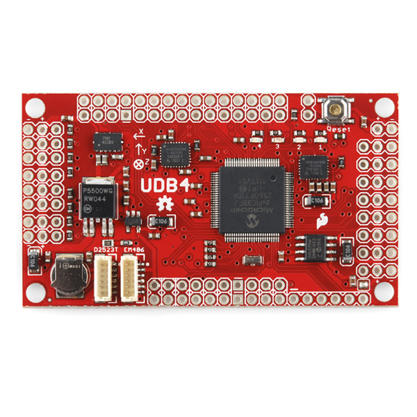
Replacement:GPS-11115. We've begun building these without the reset button populated to prevent in-flight resets. If this was never a problem for you, the reset button footprint is still present. This page is for reference only.
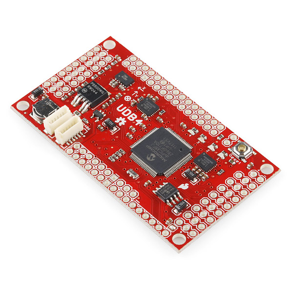
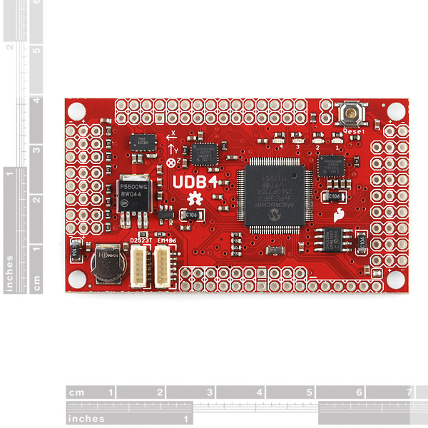
This is our latest UAV Development Board (UDB4, as in, "UAV Development Board version 4"). The UDB4 comes populated with a dsPIC33FJ256 CPU, an MMA7361 three axis accelerometer, a dual axis IDG500 gyro, and a single axis ISZ500 gyro. The on-board Invensense gyros even have enough vibration tolerance to be used in RC heli applications.
By itself, the board can be used to develop a three axis IMU controller. By addition of an EM406 or D2523T GPS receiver, it can be used to develop a UAV controller for an RC car, plane, helicopter, or boat. It comes with self-testing firmware that can serve as a starting point for you to develop your own control and navigation firmware. There is even fully functional, open source autopilot firmware available. Note: **For programming, we recommend the PICkit3. Check the related products below. **Note: A GPS module is not included. Check the related products below.
- compatible with 20-channel EM-406A SiRF III GPS
- compatible with 50-channel GS407 Helical GPS
- dsPIC33FJ256 Controller (with onboard 3.3V and 5V glue logic)
- dsPIC runs at 120MHz with 8MHz resonator and PLL
- MMA7361 three axis accelerometer
- IDG500 dual axis gyro and ISZ500 single axis gyro
- External 256Kbit EEPROM
- Up to 8 Input, 8 output PWM points
- 6-wire debug header or ICSP header
- 4 separate colored status LEDs
- On board 3.3V and 5V regulators (150mA max)
- Spare USART connection for debugging, flight logging, wireless telemetry, etc.
- 30 spare analog and digital I/O pins for debugging and interfacing to sensors
- Schematic
- Eagle Files
- Datasheet (MMA736)
- Datasheet (IDG500)
- Datasheet (ISZ500)
- MatrixPilot Code
- DIYDrones UDB Page
- DIYDrones UDB Article (how the UDB handles sustained rotations)
Comments
Looking for answers to technical questions?
We welcome your comments and suggestions below. However, if you are looking for solutions to technical questions please see our Technical Assistance page.
Customer Reviews
No reviews yet.
I cannot get my programmer to read the PIC! I am using PicKit 2,I get the error: Unsupported part (ID 07DFF) It seems the configuration 07DFF is not allowed!
Am I missing a trick here?
The dsPIC33FJ256 is in the supported devices list for the PicKit 2; are you using the latest PicKit 2 software?
Yes, I downloaded it from Microchip yesterday! After more research I find that:
"dsPIC30F/33F devices require a 4.7 uF capacitor on the Vddcore/Vcap pin in order to function properly. If not using a separate regulator to supply Vddcore, ensure that the ENVREG pin is tied to Vdd."
I see from the schematic that this capacitor is 10uF, would this make a difference???
The error I get from PicKit2 mentions the Vddcore/Vcap capacitor, I dont have it in front of me currently, I will respond with this later.
Thank you for helping by the way!
"No device detected. Ensure proper capacitance on VDDCORE/VCAP pin."
Found the issue, I had to download a new device list from microchip to support the 710"A"
http://www.microchip.com/forums/m487219.aspx
Im doing project of tracking (using GPs aided IMU) robot. Is this kit
fits for my project for tracking and data logging the robot position with good accuracy .
Im doing project of tracking (using GPs aided IMU) robot. Is this kit
fits for my project for tracking and data logging the robot position with good accuracy .
Im doing project of tracking (using GPs aided IMU) robot. Is this kit
fits for my project for tracking and data logging the robot position with good accuracy .
why #&$%& don't use 3+3+3 to have a 9 DOF UAV Board ??? TOO BAD
The board supports a separate add on magnetometer (see comments above). With that added, the UDB is "9DOF".
It is better to have the magnetometer separate, so that you can position it as far away as possible from magnetic influences. e.g. Motors, or heavy duty power wires that fluctuate in power.
For electic planes, this is a better solution than having all the chips on one board.
this should be in also in SENSORS/IMU category
Hi !
I consider to purchase this for a new quad or octo project later this winter.
Some time ago i purchased this GPS module : http://www.quadroufo.com/product_info.php?cPath=3_11&products_id=68&osCsid=f7vqktse5otla2sig3f6arrsl3
Can I use this GPS module with UDB4 or do I have to purchase a new one?
Can I use :
SEN-10530 Triple Axis Magnetometer Breakout - HMC5883L
SEN-09694 Barometric Pressure Sensor - BMP085 Breakout
I could not make your GPS module HTML link work.
The UDB4 supports four GPS units. The EM406A (available here at Sparkfun), the Ublox 5 with adapter,
the MediaTek MT3329 GPS 10Hz + Adapter , and the 50-channel GS407 Helical GPS (availble here at Sparkfun). The developer's favourite in the USA, and the favourite of Ric, our Swiss Test pilot, is the EM406A. The board only needs one really good fix per second. What the UDB needs is a good accurate fix, not a fast fix. The board will calculate the intervening positions 40 times / second using accelerometers and gyros.
The GPS breakout board module from quadroufo have the MediaTek MT3329, and support USB, 3V UART, RS232F and RS232C so that should work.
Any quadcopter projects using this controller?
I lost my quad yesterday, so no I am looking for a new controller for my new quad project.
This is the magnetometer that should work with the UDB4.
Bill Premerlani did some amazing Maths that enables MatrixPilot to automatically calculate the alignment of the UDB board with the magnetometer which makes it much more accurate and useful. This is particularly important in places where the Earth's magnetic field has a strong vertical angle. (e.g. North NY state, UK, and Switzerland).
More discussion on this is here
Does anyone know the best 3 axis magnetometer board to use with this? DIY drones has one and Sparkfun has a few. What scale factor does the UDB4 expect?
I checked the design files out and they look quite nice. The schematic is well laid out. There seems to be quite a lot of space remaining in the PCB for more traces, so you can make the V5 based on this design. I really like this kind of designs with microcontrollers and lots of sensors and actuators.
This looks awesome! I'll have to check out the full page on this thing, but quick question:
I have what I think would be a simple task, and I want to confirm it will be somewhat simple. I want to design a glider that I can drop from a high place and have it go towards a waypoint. Once there it should just circle until it hits the ground. It should just need one servo for left/right control.
Using this board and a GPS module, this should all be simple, yes? Does it have some kind of automated "go to waypoint and circle" routines? Anyway I know I'll have to read the documentation, but if anyone has a simple answer in the meantime I'd love it! :)
You're probably way ahead of me but you might want to consider pitch control for the elevator, either active control, CG control or, at a minimum, a trim tab. Depends on what how much, if at all, the configuration of the glider will change.
Sounds like an interesting project! If you haven't seen it, check out http://www.uavforge.com.
Yup, you could totally set this up right now using MatrixPilot's LOGO-based mission planning language. Loads more info on the MatrixPilot Google Code Page.
Detailed info on the UDB Logo language, including examples, can be found here.
Nice to see the full history in the blog
Here is a video link to camera targeting