- Home
- Product Categories
- Arduino Shields
- SparkFun Weather Shield

SparkFun Weather Shield
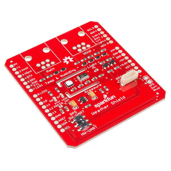
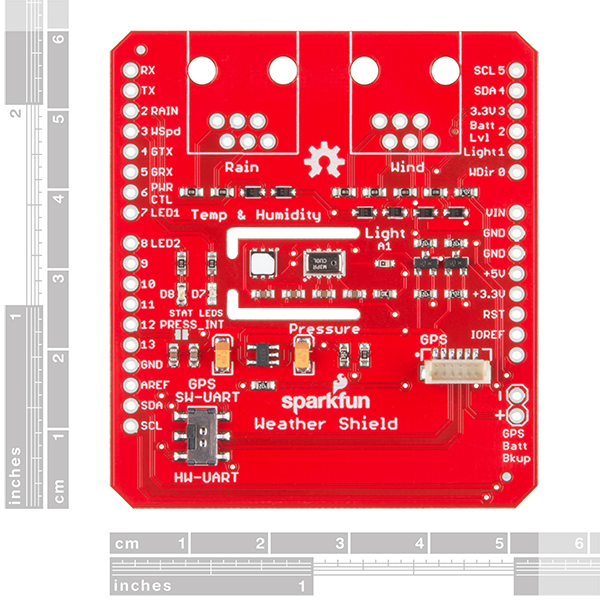
The SparkFun Weather Shield is an easy-to-use Arduino shield that grants you access to barometric pressure, relative humidity, luminosity and temperature. There are also connections on this shield to optional sensors such as wind speed, direction, rain gauge and GPS for location and super accurate timing.
The Weather Shield utilizes the Si7021 humidity/temperature sensor, the MPL3115A2 barometric pressure sensor and the ALS-PT19 light sensor. The shield relies on the Si7021 and MPL3115A2 Arduino libraries.
Each shield comes with two unpopulated RJ11 connector spaces (for optional hookup of rain and wind sensors) and a 6-pin GPS connector (for optional hookup of a GP-735 GPS module). Finally, each Weather Shield can operate from 3.3V up to 16V and has built-in voltage regulators and signal translators.
Note: The Weather Shield comes as a stand-alone board. Headers, connectors and additional sensors will need to be purchased separately; check the Wish List below or the Recommended Products on this page.
Note: This shield was designed for 5V boards, such as the SparkFun RedBoard and Arduino Uno. It will not work with 3.3V boards (like the Arduino Yun, for example) without modification.
- Humidity/Temperature Sensor --- Si7021
- Barometric Pressure --- MPL3115A2
- Light Sensor --- ALS-PT19
- Schematic
- Eagle Files
- Hookup Guide
- Datasheets
- GitHub
SparkFun Weather Shield Product Help and Resources
Arduino Weather Shield Hookup Guide V12
March 2, 2017
Read humidity, pressure and luminosity quickly and easily. Add wind speed, direction and rain gauge for full weather station capabilities.
1 of 1 found this helpful:
Adjusting for Altitude
If you are finding that the barometric pressure readings you are getting are off, you may need to correct pressure for altitude. For instance, In Denver, if the pressure is measured by NOAA 29.92"Hg it's already been corrected for altitude. The weather shield is going to read actual pressure, not pressure that has been corrected for altitude and you should expect to see a reading of about 24.73"Hg. Below is a link to a calculator that will give you a correction factor for whatever altitude your station is at. Link to calculator
Comments
Looking for answers to technical questions?
We welcome your comments and suggestions below. However, if you are looking for solutions to technical questions please see our Technical Assistance page.
Customer Reviews
4.5 out of 5
Based on 6 ratings:
4 of 4 found this helpful:
A good place to start, but requires extra effort to perform well
I purchased the Weather Shield along with a Sparkfun RedBoard, Sunny Buddy, 3.5 watt Voltaic Solar Panel, 6,600 mAhr Li-Po battery, and an Arduino prototype board. I essentially built my Weather Station following the Sparkfun Weather Station tutorial with the exception of not using the Anemometer, Wind Vane, and the Electric Imp Shield. I used the Arduino prototype board to connect a Xbee 2.4 GHz transceiver to the Arduino TX/RX connections to communicate with my base station. I mounted all of the above mentioned hardware in a Sparkfun Big Red Box sans the cover. I built a replacement cover out of 1/8 in thick Sintra and attached a 40mm X 40 mm 12 vdc exhaust fan over the Sunny Buddy and an air intake tube over the sensors on the Weather Shield to help keep the circuit boards cool during the summer. I mounted the modified Big Red Box in the suggested Ambient Weather Solar Radiation Shield. However before sealing up the Big Red Box I coated all of the circuit boards with conformal coating to seal out moisture and dirt. The Weather Station is mounted outside of my house on a pole and is powered by the recommended 3.5 watt Voltaic Solar Panel while the Big Red Box 12 vdc exhaust fan is powered by two Parallax 6 vdc 100 mAhr solar cells wired in series for 12 vdc. So far the Weather Station is working fine, but only time will tell how well the conformal coating will protect the circuit boards from the elements.
Spark fun Weather Shield
I have the weather shield up and running now over a wireless link to an inside monitor. The weather shield is fantastic. I am running it with all the options and comparing it to what I am getting from the local weather station it is about the same readings so it is pretty accurate. I am extremely pleased with the results. It saved me having to wire up a whole lot of individual sensors. Having them all on the one board is a real bonus. Thank you for an excellent product.
Ken
Up and running
Quick delivery and good support documentation had my weather shield up and running very quickly with no problems. The website with good explanation of features and links to references makes this a project that quickly shows results.
Great hardware, buggy software
The hardware is pretty good - it has everything on there that you would need. However, the software is pretty buggy. Thankfully I'm an embedded software engineer! The main issues are that if the supply voltage to the barrel jack or USB input on the RedBoard is not equal to the logic level (say, 5V vs 3.3V) then the wind direction reads incorrectly. I've not tracked down the cause but hopefully it's something to do with the analogue reference voltage that can be corrected in software. Some of the sensors (pressure, voltage, wind) give spurious readings outside the normal range. And finally the wind gust derived sensor likes to return readings with strange values - -1, 0, 1.5, 3, 4.5, etc.
Arduino Sparkfun Weather Shield
Sparkfun Weather Shield works like a charm when testing with the Arduino/Sparkfun weather-Station.ino code file. The only thing I need to do is figure out how to add a Adafruit BMP280 Barometer to the weather-Station.ino code? Any feed back would be very helpful. Over all, Very Nice board!
Eric
Any case for this to use it outside?
If you are looking for a good weatherproof enclosure we can recommend the Big Red Box. We've used it in a multitude of outdoor projects including our Photon Remote Water Level Sensor and our Wimp Weather Station (to name a few), and it has always held up really well.
It is important to keep in mind that you may need to get creative with the mounting a board inside unless it is the Big Red Box Protoboard, since the enclosure has a pretty unique interior. But if you want something that will protect your project from the elements the Big Red Box is a good choice.
Any example code/algorithm for converting the V output of the ALS -PT19 light sensor to a useful measurement like lux?
Just a friendly suggestion, for the next version, it might helpful for people trying to use this with 3.3V controllers to add an unpopulated 2 pin header for the 3.3V side of the i2c bus. I had to solder some tiny wires to mine...
Hello All, Can you teach me how to log these sensor data? Should I do it every minute interval or what interval I should send it to my server or Thingspeak?
Thank you,
Hi. Can i use this shield with an ethernet Arduino ? Maybe the ethernet port is too big ? Thank you
Can you provide a link to the board in question?
Is this compatible with Arduino Mega R3?
Yes, it will work with a SparkFun RedBoard, an Uno R3 and the Mega R3. The pinout on all three is the same.
Is this compatible with the SparkFun WiFi Shield - ESP8266? Looking to use this with ESP8266.
Hi, I cannot confirm if there is any pin contention with the ESP WiFi shield and the weather shield. I have not used the ESP WiFi shield. I can confirm that this shield works great with our SparkFun Photon RedBoard if you're looking for internet connectivity.
Hi, I am getting too much rainfall in hundreds of mm/h when solar charger is done recharging the batteries in midday, I have already added capacitors on the power cables. Any plan for adding debouncing hardware to the shield? is there any schematics I can use to know where to solder a capacitor on it.
There are no current plans to revise this hardware. The schematic for the board is available in the links above, under Documents.
Why don't you use the IOREF pin on this shield (and others)? Then we could easily use it with 3.3V systems. I suppose I can clip pins and do some soldering, but still...
Also, putting a light sensor on the same PCB as a temperature sensor makes no sense. You need to shield the temperature sensor from the sun!
how would one make an outdoor weather station with this and protect the electrical connections from the elements?
Check out this tutorial for information on making an outdoor weather station.
Can this shield be mounted on an arduino yun? maybe I understand that it has in common the 4 pin with the arduino ethernet shield... i would need to send the data collected from the sensors of this shield with the ethernet port or store it on a memory card...
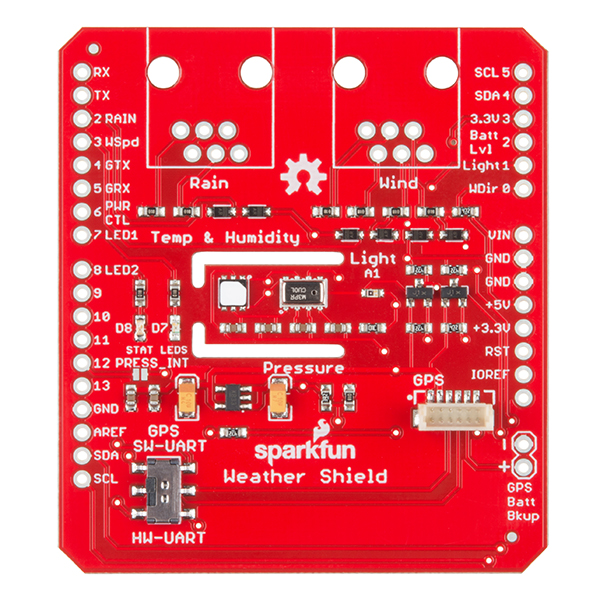
I'm curious why the sensors are segregated on their own piece of PCB?
The sensors are placed on a peninsula in order to reduce parasitic heat from the rest of the electronics from affecting the temperature sensors.
Is this compatible with Arduino due?
I believe the pinout on the Due is different from the Uno pinout that this board was built for. You may need to do some modifications for the pin connections. For more assistance on this please head over to our forums.