- Home
- Product Categories
- Shift Registers
- SparkFun Shift Register Breakout - 74HC595

SparkFun Shift Register Breakout - 74HC595
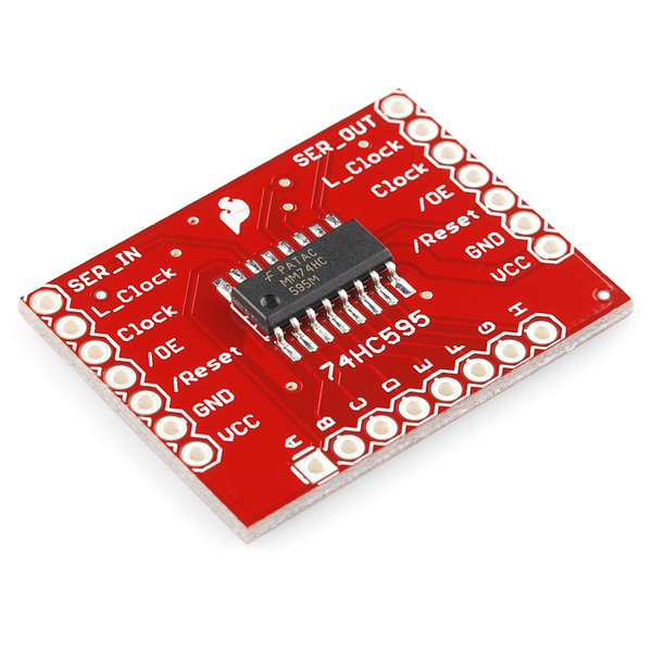
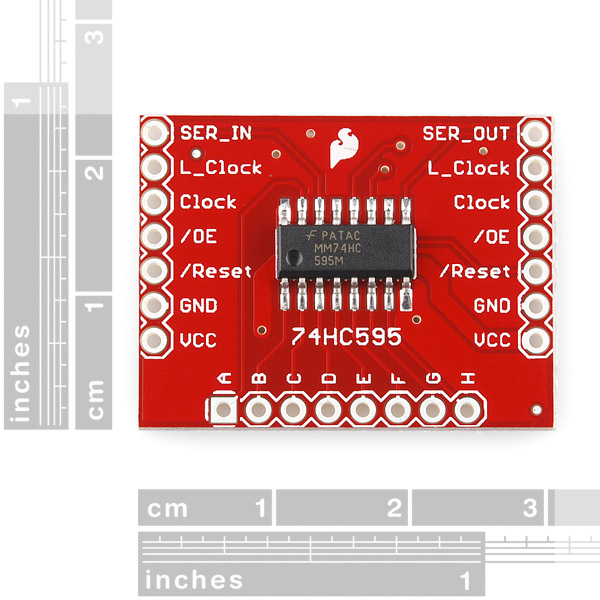
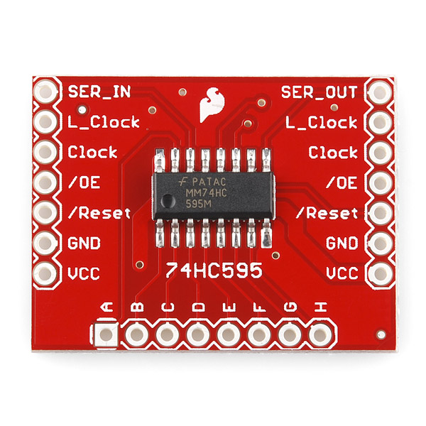
This is a breakout for the SOIC version of the 74HC595 shift register IC. Clock in data and latch it to free up IO pins on your micro. All pins from the IC are broken out to standard 0.1" spaced headers. The Serial in and out pins are on opposite sides of the board with the remaining pins carried over so that multiple shift register boards can be chained together.
- Schematic
- Eagle Files
- Shift Register Tutorial
- Datasheet (MM74HC595M)
- 7-Segment Library (Thanks Quin!)
- GitHub (Design Files)
SparkFun Shift Register Breakout - 74HC595 Product Help and Resources
Core Skill: Soldering
This skill defines how difficult the soldering is on a particular product. It might be a couple simple solder joints, or require special reflow tools.
Skill Level: Noob - Some basic soldering is required, but it is limited to a just a few pins, basic through-hole soldering, and couple (if any) polarized components. A basic soldering iron is all you should need.
See all skill levels
Core Skill: Programming
If a board needs code or communicates somehow, you're going to need to know how to program or interface with it. The programming skill is all about communication and code.
Skill Level: Rookie - You will need a better fundamental understand of what code is, and how it works. You will be using beginner-level software and development tools like Arduino. You will be dealing directly with code, but numerous examples and libraries are available. Sensors or shields will communicate with serial or TTL.
See all skill levels
Core Skill: Electrical Prototyping
If it requires power, you need to know how much, what all the pins do, and how to hook it up. You may need to reference datasheets, schematics, and know the ins and outs of electronics.
Skill Level: Rookie - You may be required to know a bit more about the component, such as orientation, or how to hook it up, in addition to power requirements. You will need to understand polarized components.
See all skill levels
Comments
Looking for answers to technical questions?
We welcome your comments and suggestions below. However, if you are looking for solutions to technical questions please see our Technical Assistance page.
Customer Reviews
4.1 out of 5
Based on 8 ratings:
Handy SiPo breakout
Makes experiencing with 74595 SiPo mcuh easier, you don't need to check datasheet all the time whether you made right connections, this chip can be quite confusing at a start, but very handy once you get hold of it. These can be daisy-chained if 8 O/P isn't enough. Good extra about this product is that it's breadboard friendly, only takes quite chunk off from prototyping space, but it's worth it. Underside of pcb is flat, so you can also install it without spacers needed, only there are tracks there so beware of S/C if you place this on metal surface. That said though, pcb quality is great, so S/C won't be issue at least anytime soon
Price is bit pricey if you need only to use this, but makes job easier to use this board
74HC595 great for linear LED display
Have been trying for months to get the max 7219 to work in a linear LED display with the Arduino Uno rev 2. But the 7219 is made to be used in a matrix or a 7 segment display. It was thought the fact that the 7219 handled 64 LEDs and the 74HC595 did eight gave the 7219 a great advantage. But breaking the 7219 out created a rat's nest of wiring. Whereas the 74HC595 with Digikey's S5482-ND female 7position right angle connector with the S1111E-07-ND 7 position right angle connector modularized the construction making testing and assembly of a line of 340 LEDs much simpler.
ok,
Pin 7 ser-out invert N.C.
Shift registers
They worked as advertised. I received 6 and they all worked. Easy to use and interact with.
Works great, pin out is a little confusing though
As someone who is a little newer to electronics I found the pin out confusing as it the labels on this breakout didnt match the pinout on the 595's in terms of names. I ended up figuring out what was what by using a continuity meter and testing each of the 595's pins to each output. Still easy to use!
Simple to use
The breakout form factor makes soldering the part very easy.
Avoid
I did receive the boards in a short amount of time, but I did actually pay for that. The boards were in good shape, but I did find that the only tutorial was for the parallel in and serial out. I did attempt to put together all examples of how to wire them up with no success. So, I did email SparkFun. Their response was prompt, but they did not have any solution. They did acknowledge that there wasn't a tutorial for this board and could not provide any assistance. I've use many of their boards with no issues, but for those boards, there were many tutorials. Unfortunately, there aren't many tutorials out on the web for this board and SparkFun doesn't have one either. At the least, I was surprised to not get any further assistance from SparkFun. This is very disappointing. If you check out the board's page at the time of this review, you will find a "Get Started With The Shift Register Guide" where it discusses shift registers in general, but the only wiring discussion/example is for the other board with slightly different pins. I am abandoning the SparkFun board and using the basic chip.
Thank you for your review. I think you might be confused about how the breakout is supposed to work though. Hopefully the data below will clear things up for you. SER_IN is the same as pin 14 on the IC L_Clock is the same as 12 on the IC Clock is the same as pin 11 on the IC /OE is the same as pin 13 on the IC /Reset is the same as pin 10 on the IC and SER_OUT is the same as pin 9 on the IC
The board is laid out with the outputs on the bottom edge of the board and power and inputs are on each side so that you can daisy chain more than one board together.
Worked as expected.
Layout makes breadboarding easier. Extra pins for using another board is a good feature.
Any possibility of incorporating a decoupling cap (vcc/gnd)? Apparently it is HIGHLY recommended, and will be more reliable for users.
Can the SER_IN, L_CLOCK, CLOCK be plugged into any 3 pins?
I don't see how you used the plug wires on the A-H holes of the breakout board. At first I didn't understand how you could even use a breakout board like that on a solderless breadboard. What's the "trick"?
You probably don't want to attempt to connect those to a breadboard, my guess is those jumper wires in the video are soldered directly to the board. You can also solder female headers onto those holes and then run jumper wires to where you need them.
Question concerning power. I know some people talk of cascading many of these things but when you start doing large chains, shouldn't current consumption be a concern? For example, lets say you cascade so many of these, say about 7, and each register collectively "uses" 160mA (20mA per channel - assume the register circuitry used to operate itself is 0A). Wouldn't the register breakout board closest to the power supply have the most "electrical stress". In other words, wouldn't the power supply pin headers closest to the power supply in my example (+5V and GND) have 7 x 160mA = 1120mA = 1.12A? And wouldn't this go beyond the typical current rating of a pin header (typically 1A)?
Anyone see where I am coming from or am I dead wrong?
From the data sheet, the total max sink or source for the IC is 70mA. You would not be able to use all channels at there max sink/source of 20mA at once, 8 Channels * 0.02A = 0.16A which is greater then 0.07A. So 7 ICs * 0.07A = 0.49A. You would need 15 ICs to pass 1A, 15 * 0.07A = 1.05A. You could use transistors on the outputs to control more current without going over the 0.07A max of the IC. Concerning your comment, yes the Vcc and Gnd pin headers closest to the power supply would have the greatest current through them. You could prevent this by running separate Vcc and Gnd wire buses to each breakout or to a group of breakouts. Hope this helps.
I would also like to know the answer to this. they should have some rating on here or they should at least recommend not connecting up so many together.
What's the maximum addressable number of inputs? Another concern about cascading multiples of these is the effective speed. If you had, let's say, 25 of these (400 inputs in total), what would the effective round-trip time be for reading data from all inputs?
While this is nice to play with and can be used on breadboard, I would like to use it as-is in an enclosure. It will save me quite a lot of time making a proto-board version ($2.95 per board is a lot less than my hourly rate and my soldering is not that good anyway! Also will only ever be making 2 of these units)
No mounting holes though. Any thoughts on best way to mount this securely (will be 2 boards chained to give me 1-of-16 selector)?
Many thanks
If you can't clamp the boards down or get them into brackets (SFE should carry some, bonus points for designing one that can be reasonably cut down to size - though not all boards are bracket-friendly; this board for example has headers along 3 of the 4 edges..), you could always take a drill to them. There's two corners that can be safely drilled through, and the top edge has some spacing right above the flame where you can make a cut-out which, together, should keep it quite sturdily in place; depicted with 3mm diameter holes: http://i.imgur.com/uqC4DMg.png . Depending on how you chain them, you may also be able to put the boards in a clamshell type setup, in which case you can run bolts/screws through both, just make sure you put some isolation material or spacers between them.
If all else fails, there's always hotglue ;)
Thanks for the reply. Not sure I fancy drilling them, though it may come to that.
Couldn't find any sort of clamping system for boards, on Spark Fun, but maybe not looking in the right place.
Just wondered whether I might rig something up from hex nylon standoffs. Cut a board-width slot about half way through each post and seat the board in to it. A nut on the threaded end through a mounting plate (or case). Could even then put a nylon screw in the top of the stand-off and pinch it on to the board. Two on one side and one near the Spark-fun logo will probably be enough, but could put an extra 2 on the side to ensure it is going nowhere.
Ah yeah, English is a bit ambigious at times, I meant that SFE should start to carry some .. and even that is ambigiuous as it could be interpreted as SFE having plans to do so. Rephrase: I wish SFE would carry some ;)
And yes, brackets are more or less what you've got in mind - which should work, except that they tend to be rail type systems. If you can get the stand-offs similar to the hole pattern - at those two corners and at the flame - that should be sufficient to keep it quite securely in place :)
I'm pretty sure I see mounting holes on the breakout board. What size bolt/screw fit inside them?
Could you use these guys to run multiple stepper motors like a dozen of them? It seems it would be possible to control the speed direction timing with them, right?
Would be good if the serial in/out clocks vcc, gnd pads where moved inwards to be inline with Pads A and H.
Hi guys. wrong name. 74HC595 should be 74LS595D. For some reason that's not noted in the above description or title.
,
Newbie question ... Can these drive the 6.5" 7-segment displays that you sell?
Don't quote me on this but I believe it would just depend on how much current you supply on the vcc pin. If not, you could just use transistors to drive them. Joel Q
Did I miss something or did the price just jump up?
Can I edit this to do analogwrite() instead of digitalwrite() with little change in .cpp? It would be nice to be able to control the brightness. By just changing:
void Shifter::setPin(int index, BOOLEAN VAL){ } to: void Shifter::setPin(int index, INT VAL){ } ?
and change digitalWrite(_SER_Pin, val); to analogWrite(_SER_Pin, val);
or do I not understand shift registers. PWM?
Yup, never mind I would need a TLC 5940...
If I l change "byte _shiftRegisters[25];" to just the amount I am using, will that speed it up a little?
Anyone know where I can get 7 pin (or more that are breakaway) 90 degree female headers?!
No but you could use this and bend them.
Oh and just cut one off.
I'm thinbking about power consumption. So if I put say 10 of these together that gives me 10x80 LEDs possible. If I turn on all 80 LEDs are they really all on at the same time? How do I manage power consumption? Sorry I'm pretty new to all of this.
Yes,check out the bildr link above, I have I think 7 going at once. You just need to power the first one with a 5v wall connector or similar if you want to power than many. The traces on the power pins are much larger than normal so that you can string 20 of these together if you want.
Yes, they will all be on. But a) they will be very dim or b) the shift register will explode. Why? These can only handle +/-35mA and dissipate 500mW of heat...
The shift register will not explode. Sorry. It is 500ma per chip. Not per string.
I'm a beginner and I like it.
I saw 6 pin right angle headers but this needs 7 pin headers. I still don't see them here. What about offering some of those here. I would prefer to get them from Sparkfun the same time I order these Shift Register Breakouts.
We have been doing a similar breakout board for the TPIC6B595 Shift Register 8-bit High Power IC. Its a bit more expensive because of the higher cost of the device but it is a great way of driving high power devices whilst just using up 3 pins on the Arduino. It also comes with the pin headers, a dip socket (incase you blow the chip) and a decoupling cap as standard.
http://proto-pic.co.uk/products/Shifter-kit-v1.1.html
Now you need a 7 pin right angle header (both male and female) to cleanly chain them together. That is scheduled to come out next week, right?
A decoupling cap would have been nice...
(this was in reply to Chris, but the board screwed it up)
I'm not convinced. A "beginner" will more than likely be using a breadboard for their project, not some breakout board for an SOIC chip that requires jumpers or wires to be soldered around the edges to be usable. The DIP variant will be far more useful for most beginners.
This board is more appropriate for someone who wants to have a shift register in a design but doesn't want to solder up a DIP chip or socket.
This was actually my submission for a new part. We have a ton of people coming to our site ( bildr ) wanting exactly this.
We have been doing a lot with large chains of these and most people are not not wanting to make their own boards, or leave it on breadboard. This will save a ton of wire for a lot of people.
Ill be revamping the article to cover specifically this part, but we have code that allows you to chain these together and get individual pin control from them. Very useful for when you need 500 solenoids connected to your arduino.
Why don't they just buy some sockets and stick them on a protoboard? This breakout board seems like a giant waste of space compared to how tightly you could pack these chips into a protoboard.
This makes it easy to put some right angle headers on them and chain 100 together without having to wonder if there is a lose wire in the registers somewhere.
As weird as it may seem, this will be helpful for people, and actually mean less soldering, and less wire.
You sir, deserve a cookie. This is awesome, expecially when a project goes out into the wild. How a bout one for the 74HC165N
Wouldn't the SOIC version on this breakout be significantly larger and more expensive than just using the DIP version?
Indeed, I note that this is 2x the cost of your own DIP version, and significantly larger as well. I don't see the point?
Larger, yes. More expensive, yes again.
This has the pins broken out in a logical, easy to use configuration that would be great for a beginner.
I'd say that's worth 3 bucks.
;)
I allows you to really easily string a bunch together.