- Home
- LED RingCoder Breakout

LED RingCoder Breakout
Replacement:BOB-11040. The new version of this board gives full RGB control for our RGB Rotary Encoders. This page is for reference only.
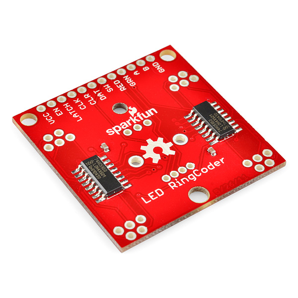
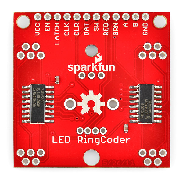
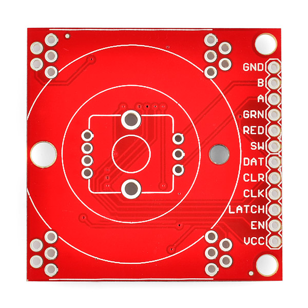
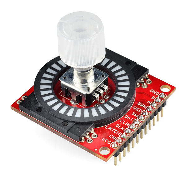
This breakout board gives you a pretty slick interface for rotary input. Since rotary encoders turn continuously it can be difficult to imagine where in your range of values you might be at any given time. This board uses two 8-bit shift registers to control a circular LED bargraph which can be used to indicate the virtual position of a rotary encoder. The footprint for the encoder matches up with our illuminated rotary encoders for optimum 'blinky-ness'. The shift register inputs and rotary encoder lines are all broken out to standard 0.1" headers.
Note: This is the breakout board only, you will need to populate your own rotary encoder and circular LED bargraph. Both parts can be found in the related items below.
Note: Read Jim's comment below. It's best to run this board at 3.3v until we come out with a revision.
Comments
Looking for answers to technical questions?
We welcome your comments and suggestions below. However, if you are looking for solutions to technical questions please see our Technical Assistance page.
Customer Reviews
No reviews yet.
Thanks for keeping us honest loyal SparkFunners...
If you've got this board, try running it at lower voltages. Running it at 3.3V, I measure 13mA on a diode when only that LED is on, and 12mA when all are on. No noticeable difference in brightness (to my eyes).
Running it at 5V: current on a LED with only that LED on sits at about 34mA, while when they're all on each LED runs at about 24mA. There is a slight difference in brightness in this case, and the HC595 is certainly not thrilled with the amount of power it's dissipating.
Time to eat some crow; this is a pretty lazy design. We'll get on a revision, so you can run it safely at 5V.
Has anyone come up with a revision for this yet?
I bet you can do all of this with 4 wires+1 (VCC,GND,SCL,SDA,+INT) using 2 ICs. And have better control without the waist.
Operating power supply voltage range of 2.3 V to 5.5 V
5.5 V tolerant inputs
-40 °C to +85 °C operation
NXP IC's: PCA9554 and PCA9635. The PCA9554 can handle the LEDs and trap everything the encoder can throw at it- saving code. The PCA9635 is totally programmable: From ON/OFF, Programmable LED brightness, Programmable group dimming/blinking mixed with individual LED brightness. IF set up correctly both chips are addressable- allowing 7+ boards using the same 5 wires.
This is a classic Sparkfun design; there's no power supply voltage specified for the board, no current limiting resistors for the LEDs, and the LED driver chips are 74HC595 (pictured), not 74LS595 (as in the schematic diagram).
This board will probably work best using a 3.3V supply (unless 74LS595's are really used, in which case it will only work at 5V). The LEDs won't be as bright as they could be, but at least the component overloading is minimized. At 5V, probably both the LED and the '595 chip current ratings will be exceeded; it may work, but not for very long.
Wow. Harsh man.
He's right though.
Well, at least it's not a $15 breadboard power supply.
Give them a break though, this board was designed on the 11th day of the 26th month of 2005.
Yes, I hate non-ISO dates.
That date is the standard format for the US.
I mean, we still use feet and inches, what would you expect? ;)
You mean year 5?
Given the strange date I assumed it also had a Y2K problem. ;-)
Unfortunately true. There's no pads for adding resistors, and the max source current per pin is 35mA, which is above the 25mA max of the LEDs. Output clamping is 20mA, so where does the 35mA come in?
http://ics.nxp.com/products/hc/datasheet/74hc595.74hct595.pdf
Alternately, most drivers are sink drivers, and the ring needs a source driver. The few chips I've seen as source drivers are PWM units which might be more complex than they wanted for this application.
Perhaps I shouldn't post after drinking heavily.
Anyway, the clamp current limit is for externally applied voltages that are over/under Vcc/Gnd, respectively. It's the maximum current that the internal clamp diodes can handle. The 35 mA value is the maximum that the output driver can source or sink.
The data sheet also specs the max VCC and GND currents as 70mA, which means either the chip will possibly burn out or the brightness will possibly vary as you increase the number of non-current-limited lit LEDs.
Also note there is a max power dissipation for the SO16 package of 500mW which, if I'm interpreting things correctly, would mean that you can only have 12.5mA per channel if all channels are permanently lit.
Please correct me if I'm wrong.
What, you don't want the brightness of the LEDs to change based on the number of LEDs on? Dude, that's not a bug -- it's a feature! :)
+1 for this being another awful SFE design.
It doesn't seems easy to chain 2 ringcoders pairs of shift registers.
That would be useful to add a "SERIAL OUT" on the next revision board, as 74HC595 are chainable.
Is there any workaround with this one ?
I'm wondering the same thing. I want to light up just one segment at a time, instead of a light and the one across from it. Anybody have any ideas?
that doesn't seems possible. i didn't open the ring but the number of pins is insufficient to power individual leds.
It's possible cuz its on shift registers. I actually figured it out...it was a code issue. Thanks!
Since there appears to be so many armchair design engineers willing to help out, maybe Sparkfun could post designs and specs for a brief review before comitting them to atoms.
This is a good idea. Design by committee is tough, but filtered input from the masses could go a long way to improving several of the products. Personally I'm not so big on shift-register designs, preferring an I2C connection. Where I've gotten stung before from Sparkfun is carving up boards to get to pull-up/down configuration pins that were tied directly to ground or vcc.
I personally hate Common Cathode LEDs.
GB if I remember right the NXP’s I2C PCA9635 can sink 25 mA and source 10 mA at 5 V.
But can’t you use some type of PnP MOSFET to source current for this Common Cathode LED Bargraph (using the mosfet like an logic inverter)?
Yes you still need the resistor to limit current. I just remember doing this for one of my logic classes back in college to run a 5 x 7 dot matrix LED.
despite the fact that you nerds are a little over nerdy, its still a cool product and you can find a use for it.
constructive criticism is always much more appreciated than a man with a
terrible attitude