- Home
- Product Categories
- Encoders
- Rotary Encoder - 200 P/R

Rotary Encoder - 200 P/R
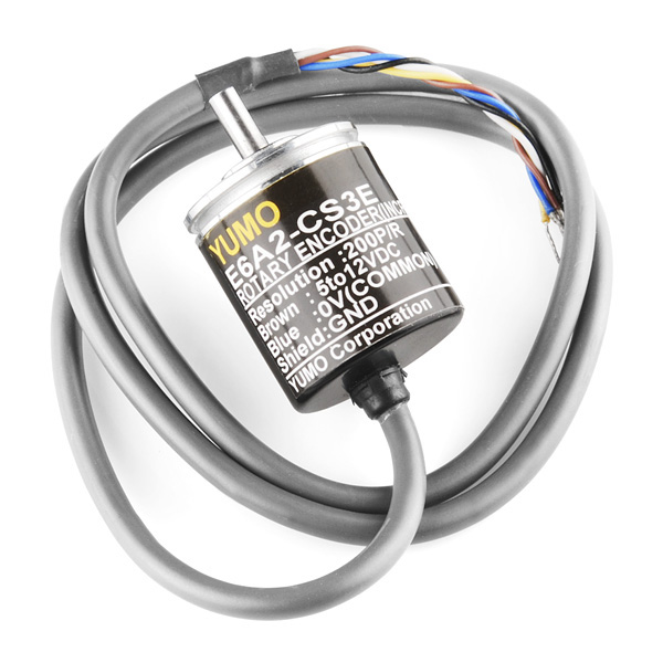
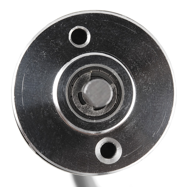
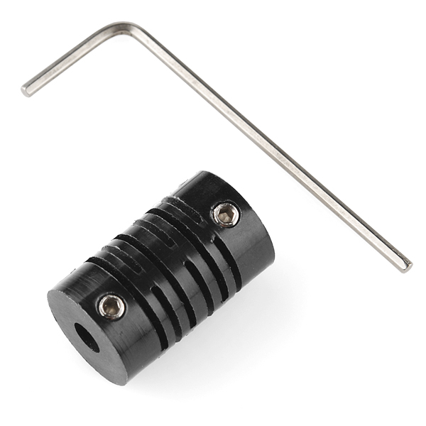
This 200 pulse per rotation single-output encoder outputs electrical pulses which you can interpret using a microcontroller to find the position of the input shaft. This allows you to add feedback to motor control systems. Encoders of this kind are often used in balancing robots and dead reckoning navigation. The encoder comes with a set screw coupler which will attach to any 4mm shaft.
- Resolution: 200 Pulse/Rotation
- Input Voltage: 5 - 12VDC
- Maximum Rotating Speed: 5000rpm
- Allowable Radial Load: 5N
- Allowable Axial Load: 3N
- Cable Length: 50cm
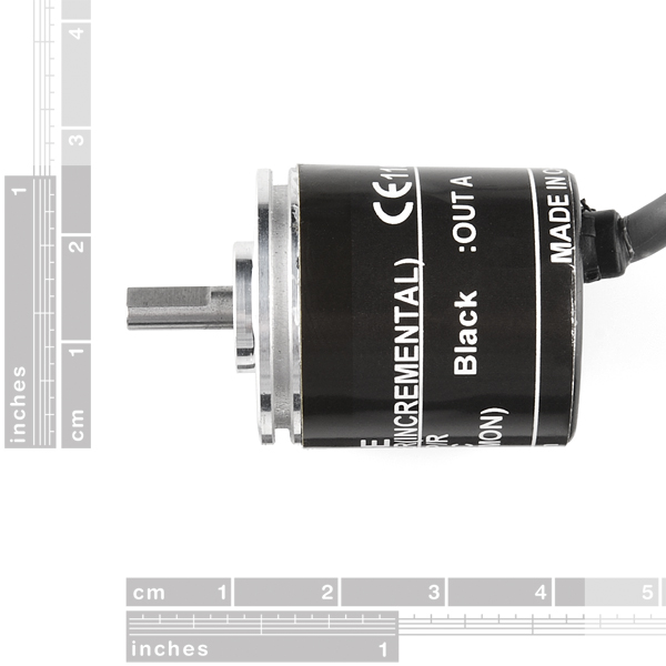
- Shaft Diameter: 4mm
- Datasheet (E6A2-CS3E)
Rotary Encoder - 200 P/R Product Help and Resources
Example code for COM-10790
You can find some simple example code for this part here!
Comments
Looking for answers to technical questions?
We welcome your comments and suggestions below. However, if you are looking for solutions to technical questions please see our Technical Assistance page.
Customer Reviews
2.3 out of 5
Based on 3 ratings:
0 of 1 found this helpful:
Fault on receipt.
Output stage was floating, pulses didn't return to zero,
Its unidirectional!
It works great except you can't tell if its going CW or CCW because it only has one data output! Useless! I can't even think of a application that doesn't need to know what direction it's going in. SparkFun can you please list this on the site so nobody makes the same mistake as me.
Sorry about that! We do state that it has a single output in the description though. COM-10932 is the dual output version of this encoder and can tell you what direction it's turning.
Easy to get up and running
This was just the ticket for making my Rolatape 32-623 display. This is a professional grade trail survey instrument but only has a mechanical counter. An arduino and a bit of programming with this encoder is all that was needed to make a highly accurate counter and large easy to read display
I need help. I am exhausted and nothing seems to work for this encoder. How do I wire it including resistors etc?Can someone help with sample code? Nothing I have tried returned any results. I do not need directional travel. I will be calculating speed of a manufacturing line so this is what I thought I needed but I cannot get any output signals.
The data sheet says "Mounting Bracket E69-1 supplied with A6A2-CWZ encoders", but I don't see any brackets in the product photos. Are brackets included? (I see there are two M3 mounting holes on the face, but I was curious of the clips are included or not)
This is the E6A2-CS3E and no mounting bracket is included. You do get everything that's in the photos though.
What's the difference between this and COM-10932, which is $10 more expensive and has "(Quadrature)" in the name? Both have the same datasheet as far as I can tell.
The "example code" does not count quadrature correctly. It makes the common mistake of looking for an edge on one channel and then counting up or down depending on the state of the other channel. It'll look good when the shaft is being turned steadily in one direction, but it won't work when the shaft is moving back and forth by small (1/200-revolution) angles.
When the encoder shaft is being moved steadily in one of its directions, it repeats the sequence 00 -> 01 -> 11 -> 10 -> 00. In the other direction, the sequence is reversed: 00 -> 10 -> 11 -> 01 -> 00. But a reversal can happen at any time in the sequence, e.g: 00 -> 01 -> 11 -> [reversal] 01 -> 00. The shortest pattern with a reversal is 00 -> 01 [reversal] -> 00 (repeating).
Now imagine that the second bit is the one being treated as a rising-edge interrupt. Rising edges of this pin will be seen repeatedly, and the "other bit" will always be 0. That means that with this input waveform, the count will always increase even though there is no net motion on the motor shaft.
Another way to look at it is: you can have one lost count at every reversal.
In CNC positioning applications, this is unacceptable. Depending on your application, the inaccuracy may be less important than the speed or the "load" on your microcontroller (e.g., speed control applications)...
You are correct. I wish I had a dollar for every quadrature interface example that used one of the outputs as a clock and the other as a direction! The correct way is to configure the processor with TWO interrupts, one for each pulse and to trigger on change (ie BOTH rising AND falling edges). Then use a state machine to read the new state of the two inputs and based on the previous state decide if the direction was forward or reverse. AVR micros have an interrupt on pin change (by port) which can be used for this rather than using two discrete interrupt inputs.
Another way to do it is to poll the two inputs and if the new state is different from the last process as described above. You can set a timer to establish the poll rate, which would be determined by the number of pulses per revolution and the max expected speed of rotation.
BTW this encoder looks like it's designed for coupling to a motor, there are better units (and cheaper!) for use as digital panel pots with knobs.
if you have only one interrupt input you can use a xor gate to detect the edges from both lines
Does this help?
https://www.circuitsathome.com/mcu/reading-rotary-encoder-on-arduino
Just wondering if someone might be able to help me out. I put Output A and B on a scope and this is what it looked like.
Curious if anyone can explain why it looks like this. I've got blue to ground, brown to 5V (from the data sheet) and output A is blue on the scope and output B is yellow.
Thanks :)
Noob question: If I only need one direction, could I only use one output signal and ignore the other one?
This product has a max rpm at 5000. Does that mean you won't be able to read a true signal after 5000 rpm? Or would the encoder break at greater speeds? Any inout on the matter is greatly appreciated. Thanks
seriously.... every time I see something cool to buy from here at work I say: "I'll go home and buy it".... I get home and they run out.... they were all in stock before I left work, and now they're all gone!
Is this Features of this Motor sufficient for Toy Helicopter Build???
Does anyone know if the coupler is flexible? thx
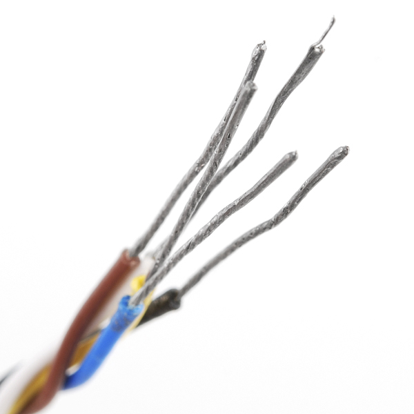
I just received one of these... Only has 4 wires, not five like shown. Is it a bad part I got or wrong picture?
Ok... so the wires werent stripped and in the cable...
This encoder is actually a quadrature encoder. Part number I received was "E6A2-CW3C". It is an open collector output, so use a step up resistor on the A and B wires. GregR's snippet should work.
The Chinese really do suck at dimensioning, but I suppose that's why this knockoff OMRON part is 10x cheaper...
http://www.austriamicrosystems.com/eng/Products/Magnetic-Encoders/Rotary-Encoders
Seem to be excellent encoders at low price points.
RLS also makes a range of these
http://www.rls.si/default.asp?prod=modules
This encoder is way too expensive given its limitations.
Thanks for clearing up the non-quadratureness.
Any plans on getting the quadrature model? With Z? And higher count?
You could get these pretty cheap from another source (in kit form) but their price has more than double. Don't ask their price for a sealed unit.
Ok, so no velocity control (as others said a single channel quadrature). HOWEVER, this is perfect for high accuracy speed control. Run it into a counter, check it on a timer interrupt and you can close a really accurate speed loop for a motor.
Wow, people are really ripping sparkfun a new one on this product's description and example code. Feels like I'm on HackADay before this post: http://hackaday.com/2011/07/27/hackaday-comment-policy-were-cleaning-up/
We made a technical mistake and got called out on it; I don't think the tone here is quite the sort of inflammatory hostility Hack a Day are trying to address with that post...
Darn it! The other comments about this not being a quadrature encoder are correct. This outputs a single pulse.
The datasheet explains the last three characters of the model number "S3E". "S" is for "singleness output 'A'". (The quadrature models have a "W" instead of a "S".) "3" is the voltage rating 5V to 12V. "E" is the output type "(NPN) Voltage output".
It can not be used "as a very precise input knob". There is no direction information for you microcontroller to read.
These could be used to monitor motor speed as long as you know which way the motor is turning.
DARN, DARN, DARN! So many uses are lost by not having two pulse channels.
D GregR is correct. This is a single output device that will not give you direction. You must have the A and B outputs that are 90 degrees out of phase to get direction. The pictured case even shows "Black :OUT A" as the only output signal. Sparkfun needs to update the description or get the correct product.
Heres an arduino code snippet for quadrature encoders
Thanks for the start, @Ocean\ Controls! Here's a full Arduino sketch with wiring instructions in the comments header.
This code does not seem to work for this encoder. Works fine for a quadrature type with 2 outputs. This guy only has one.
If you read the data sheet you will see that the E6A2-CS3E model is a "singleness output 'A'" [sic] type.
This means that it is neither a quadrature nor gray code encoder (which are not the same thing btw) and you cannot determine direction, only speed, and position in one direction, with one signal.
Also backing this up the datasheet says "The white (green) and orange (yellow) lines of the single type (E6A2-CS) do not output signals (no connection)".
You would need the E6A2-CW3E for a quadrature output and E6A2-CWZ3E for quadrature with Z (origin) signal.
Would someone from Sparkfun's Staff be so kind to confirm this please? I wouldn't like to buy this product and discover this information once I have it in my hands :(. Thanks!!
He's absolutely right! Although this product had originally been entered into our catalog as a quadrature encoder (I suspect we ordered a different one than we intended) this is, in fact, a single-output incremental encoder. Still very useful, but it won't give you directional information. My apologies!
Thanks for clearing it up :) That's what I like from Sparkfun, you made a mistake (everyone does from time to time), assumed it and then you've corrected it.
Cheers!
Think this would work with 3.3V?
looking at the case and the datasheet, that seems unlikely. but, you can still try ;-)