- Home
- Product Categories
- Encoders
- Rotary Encoder - 200 P/R (Quadrature)

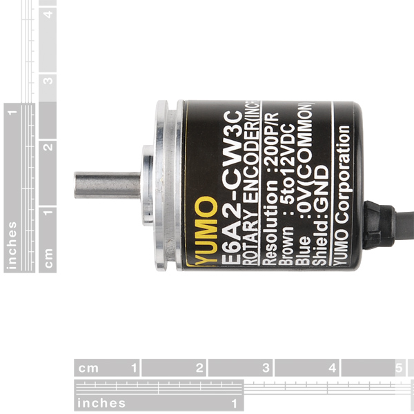
Rotary Encoder - 200 P/R (Quadrature)
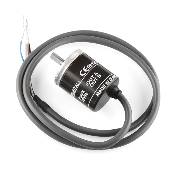
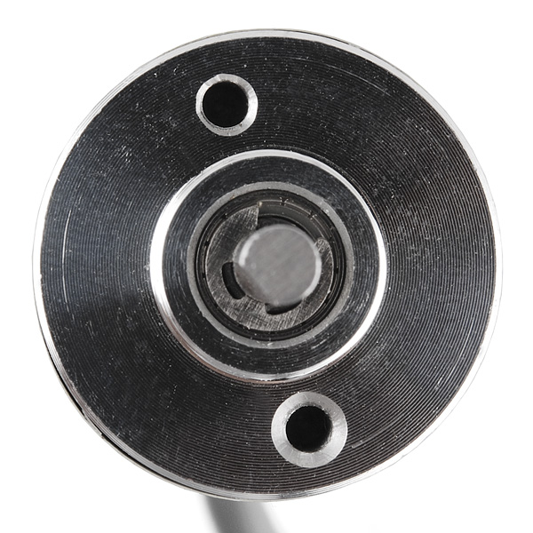
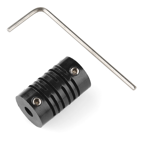
This 200 pulse per rotation rotary encoder outputs gray code which you can interpret using a microcontroller and find out which direction the shaft is turning and by how much. This allows you to add feedback to motor control systems. Encoders of this kind are often used in balancing robots and dead reckoning navigation but it could also be used as a very precise input knob. The encoder comes with a set screw coupler which will attach to any 4mm shaft.
- Resolution: 200 Pulse/Rotation
- Input Voltage: 5 - 12VDC
- Maximum Rotating Speed: 5000rpm
- Allowable Radial Load: 5N
- Allowable Axial Load: 3N
- Cable Length: 50cm
- Shaft Diameter: 4mm
- Datasheet (E6A2-CW3C)
- Example Code
Comments
Looking for answers to technical questions?
We welcome your comments and suggestions below. However, if you are looking for solutions to technical questions please see our Technical Assistance page.
Customer Reviews
5 out of 5
Based on 1 ratings:
Don't forget the pull-up resistors!
On the Arduino, you can use the internal resistors by defining your inputs with INPUT_PULLUP.
This is my code to use it:
I´m trying to read the encoder with the Arduino and everything is okay. But when I read an analog signal the arduino only reads the analog input. I connect both GND, but its still not reading. Does anyone know how can I fix this? Thanks
as opposed to the example above, here's some code that will get this working right-away in true quadrature fashion. [model #E6A2-CW3C]
sorry if it is wrong to post this here, but it's free to the world, have spark-fun!
lol - that looked a lot better when I pasted it!!!
Great little encoder for the price. Here's my experience:
Easy hookup, especially since the wiring is documented on the encoder. Wish other products did this! Ground, +5, Out A and Out B. I wired the outputs to my Arduino interrupts, in the case of my Uno that's D2 and D3.
Don't forget the pullups between each output and +5! (I did at first.) The output is open collector and so won't go up to +5 otherwise. I used 10K.
I used the Quadrature encoder library QuadratureEncoder.h pretty much right out of Dr. Rainer Hessmer blog here. Thanks Dr. Hessmer!
In Arduino 1.0 Wprogram.h has been replaced by Arduino.h
In my sketch I copied the example usage from the library and added the following:
Serial.println ( encoder.getPosition()); delay (10);
Don't forget to initialize the serial port in setup()
That's it! worked right away.
I'm having a hard time figuring out how to wire the shield wire. It says "Shield: GND" on the rotary encoder. But it's very confusing because the blue wire is "0V(Common)", which is what I connect the negative terminal of the power source to (I think). And the negative side is usually called "ground" right? So, Why is the shield called ground? And what do I connect that to? I'm planning to use an arduino mega with the encoder.
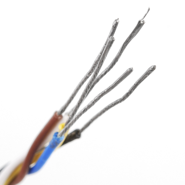
Hmm... Why is there a photo of 5 wires? This rotary encoder only comes with 4 wires, there is no yellow wire. I'm new to all this stuff, a wiring diagram would be fantastic
Mine came with a wiring diagram. Also the data-sheet has a wiring diagram.
As for the 5th wire. Mine also has a yellow wire, but it is clipped short. No doubt a 5 wire cable is used for all of their encoders and is simply disconnected for this model. Ignore it if you have it and don't worry about it if you do not. Good luck.
I played with an implementation of a quadrature encoder on Arduino and documented some of my understandings / learnings. Might help someone understand the basics...
Index tic would be nice.
Outputs gray code? What I could gather from the datasheet is that the encoder outputs quadrature signals, is that the case really?
According to the photos and the datasheet, it's definitely quadrature: two square waves, 90 degrees out of phase. These two signals give direction of rotation, as well as the usual speed.
It's a kind of gray code, since only one bit changes at a time, but because there are only two bits it only counts 0, 1, 3, 2, 200 times per revolution.
0 0
0 1
1 1
1 0
how one could mount it on a DC motor?
There are a few ways, but you don't really mount it on the motor itself, generally. For small motors, one of 2 solutions:
a) On the shaft of the motor, in addition to whatever you're using for drive, you can have a gear/pulley that links to the encoder. Depending on your setup, this can also let you have a large gear/pulley on the motor going to a small gear/pulley on the encoder, so a 200 ppr encoder will have a much finer resolution in terms of motor revolutions. So whatever you've bolted your motor to, bolt your encoder to the same thing and have gears/belts/whatever between them.
b) Attach the encoder to the thing actually being driven. We use encoders like this in theatre a lot for automated scenery, and for a lot of things, you don't actually care about how far the motor has moved, only how far the scenery has moved. While they are almost always the same, if your drive system has any potential for slip (belt drive, friction drives, etc), you want to measure the thing moving, not the motor itself.
many thanks indeed for the detailed reply. could you direct me to some practical examples online?
Sorry for the delay! I'm in the middle of moving house, but I'm also in the middle of building a mini motion control system, so I'll put up some photos and instructions for both those approaches.
This would of been very handy for when I converted my L1011 altitude encoder to digital output for flight simulation.. Better yet, a board that could interpret the 400hz ac resolvers that were originally inside the instrument would of been best!