- Home
- Product Categories
- Kits
- SparkFun Simon Says - Surface Mount Soldering Kit

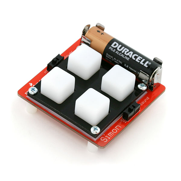
SparkFun Simon Says - Surface Mount Soldering Kit
This is the latest version of the Simon SMD soldering kit, the surface mount version of our popular Simon Kit. It's considered an intermediate kit for people who have soldered before and wish to learn how to solder surface mount components. Don't worry, we've added extras of the small components to help you out if you misplace a super tiny resistor.
We've made a lot of subtle changes to the latest version which make it easier for someone to solder with little surface mount experience.
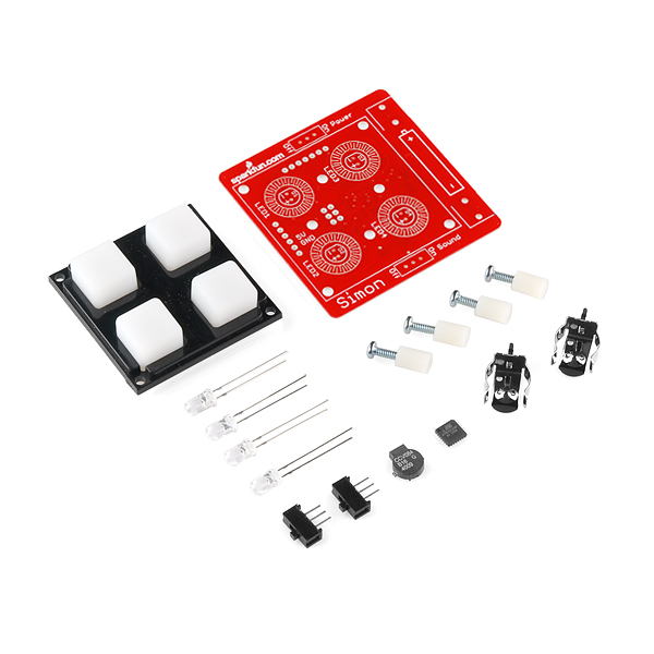
Through-hole components:
- 1 x ATmega328 based Simon PCB
- 2 x AA Battery Clips
- 2 x Slide switches
- 4 x LED (Yellow, Blue, Red, Green)
- 4 x Screws
- 4 x Plastic Standoffs
- 1 x Rubber 4-Button Pad
- 1 x Button Pad Frame
SMD components:
- 6 x 330 Ohm Resistors
- 3 x 10k Ohm Resistor
- 1 x 47uF Capacitor
- 1 x 10uF Capacitor
- 3 x 0.1uF Capacitor
- 1 x MBRA140 Diode
- 1 x 22uH Inductor
- 1 x NCP1402 SOT-23-5 IC
- 1 x ATmega328 TQFP IC (Pre-Programmed!)
- 1 x Buzzer
Replaces:KIT-09882
SparkFun Simon Says - Surface Mount Soldering Kit Product Help and Resources
Simon Says Experiments
October 21, 2010
So you've built up a Simon Says kit? What next? This tutorial will get you up and running with Arduino software, guide you through a few example sketches, and send you on your way to create your own. Careful, this stuff is highly addictive. :)
Core Skill: Soldering
This skill defines how difficult the soldering is on a particular product. It might be a couple simple solder joints, or require special reflow tools.
Skill Level: Competent - You will encounter surface mount components and basic SMD soldering techniques are required.
See all skill levels
Core Skill: DIY
Whether it's for assembling a kit, hacking an enclosure, or creating your own parts; the DIY skill is all about knowing how to use tools and the techniques associated with them.
Skill Level: Noob - Basic assembly is required. You may need to provide your own basic tools like a screwdriver, hammer or scissors. Power tools or custom parts are not required. Instructions will be included and easy to follow. Sewing may be required, but only with included patterns.
See all skill levels
Core Skill: Electrical Prototyping
If it requires power, you need to know how much, what all the pins do, and how to hook it up. You may need to reference datasheets, schematics, and know the ins and outs of electronics.
Skill Level: Rookie - You may be required to know a bit more about the component, such as orientation, or how to hook it up, in addition to power requirements. You will need to understand polarized components.
See all skill levels
Comments
Looking for answers to technical questions?
We welcome your comments and suggestions below. However, if you are looking for solutions to technical questions please see our Technical Assistance page.
Customer Reviews
5 out of 5
Based on 2 ratings:
1 of 1 found this helpful:
Useful training tool
I bought this to learn SMD soldering. The instruction booklet is well written and explains what to do. And seeing the thing work after assembly proved I was able to solder successfully.
I have been assembling several of these kits. The tricky part has been to get the DC-DC converter (MCP1400) to put out a 5 volt level. A shame the kit doesn't come with an ISP header, I would like to write my own version of the game.
The assembled kit however looks really nice once it is working.
The ISP pads are broken out - you may be able to get your programmer working with them by inserting a few pins into your programmer's plug and nudging those to the plated insides of the pad holes. Also consider ISP Pogo Adapter :)
I like the last line on the first page of the "Assembly Guide". It says "Once assembled – bring to Matt or Nathan for programming". Sorry, but that makes this $24.95 kit way too expensive for me. $24.95 for the kit and a drive of over 1500 miles, one way, to program it. Although I do have to admit that I like the personal touch of Nate doing the programming!
Hah! Good catch. Thanks for not holding me to it ;)
Methinks they just posted instructions from one of their soldering classes...
I built this kit. However, the speaker is not working. I replaced it with a speaker from another kit but to no avail. I also tried jumping the switch manually to make sure it wasn't the switch but that didn't help. Can I use a voltmeter across the speaker, what voltages would I see if it's working? Any ideas?
Sorry to hear you are having trouble with the buzzer. It might be worth watching the voltage on either side of the buzzer, however I'm not confident that your multi-meter would react fast enough to see anything. The "buzzes" are really quick, and they are actually a PWM signal, which multi-meters aren't the best at seeing. If you have a scope, that would be a great way to verify the signal is working.
Another approach: I would recommend checking the leg off of the IC that controls the buzzer for a good solder connection. It is the upper left most leg on the left side of the IC. If the leg is not soldered properly (or there is an accidental bridge to the adjacent leg), then this would prevent it from actually making noise. Hope this helps!
Hello, I managed to break the inductor, do you guys have a part number for a replacement unit ? Thanks !
Hi NatL, Sorry we do not carry that inductor alone on our website, but you can pick one up from digikey here
Hope it goes well!
Thanks ! I had already checked digikey but with 10 of thousands of different models this link will be very useful :)
This kit is nice. I used the stencil, paste and a toaster oven (Yes, it is non food). I bridged some pins due to a small error while placing the chip, so the ATMega needed a lot of going over with copper braid, but it worked great.. The hardest part was telling the 10uF cap from the diode. Great kit lots of fun.
Having messed up my first attempt, here is a list of the things you need/want/makes it more fun for this kit, starting with the needs (sparkfun products linked when available): A soldering iron, solder, solder wick, tweezers, something to trim the PTH leads (diagonal cutter, flush cutter, or similar), and a hoof tip for your iron for the ATmega328. If you can do it with a standard tip you are some kind of savant. The wants: A soldering station, flux (especially for the ATmega, but useful for all the SMDs), a chisel tip for the rest of the SMDs, Chipquick for if you mess up, and possibly some sort of magnifier to read the printing on the SMD parts. The make-this-kit-more-awesome-when-you're-dones: A 5V FTDI breakout, Some headers, and a photocell, will let you reprogram the kit to do more cool stuff.
Is there a version of this Kit that comes with the tool similar to the thru hole version, but also a pair of tweezers?
A nice little kit. After losing and finding one of the 0.1uF caps for the SECOND time I abandoned the recommended soldering method in the guide. Instead I fluxed both pads, maneuvered the cap onto the pads with tweezers and held it down, and then carried solder on the iron to the component leads.
Some thoughts on the kit:
1) The covering tape for a few components were brushed with a bit of color, but there was no info on what component was used with each color. The coloring also obscured the component markings, which meant that, if you go in order of the guide, you might have to open several packages to find the next component. 2) The front page of the guide mentions that flux is needed to complete the kit, but its use is never described in the instructions. I think flux is essential, esp for the microcontroller pins. 3) Two other items are needed for completing the kit: a good source of magnification (10x is nice), and good lighting.
My hunch is that this kit is typically used in a guided setting, with one or more instructors offering pointers. As a result the guide is not quite all there for people flying solo.
All in all I'm very pleased, but then I watched a pile of YouTube videos on SMD soldering before trying this kit. If I had less experience it might have been more frustrating. Flux is your friend!
I just pulled mine from my junk desk. One of the LEDs was broken and I was determined to fix it. Broke out my multimeter, found that there was positive voltage getting to the right pin on the LED. Found no voltage across the LED (so probably not a bad LED). I thought the ground side of the LED wasn't making good contact with the ground plane. So I cranked up my soldering iron a bit to "ground plane temperature", added a bit of flux, scraped some of the ground plane back to make sure it gets a good connection, and went at it. The connection I made was fine. Still no go. Then I shorted the ground LED wire to the ground pin. Works fine. Examined the traces on the PCB more closely. There's PCB error on mine! The ground plane goes half way, but fails to connect to the rest! So I just added a bodge wire from ground to the ground LED pin. (A broken ground plane didn't do anything in their QR department?) The board is labelled Simon and the date is 5/3/10. Works fine now, but definitely a learning experience in trusting Sparkfun's iffy PCB layouts.
Hi, Can anyone please point me to a company which can help us develop the rubber button switch for a product i am working on. Can we buy rubber button pads of different sizes for prototyping anywhere?
Just finished assembling mine, and nearly everything works. My only problem is that LED4 (red on my assembly) is dim during normal operation. It does shine brightly when first powered on, but is barely visible after that - especially with the sound on. Any thoughts on what I can check?
EDIT: I've fixed it. I'm not sure, but I think I had a hidden solder bridge between pins 31 (TXD, which I knew from prior Arduino experience goes high on boot) and 32, with another very tiny trace of a bridge between pins 1 and 2 (which control the buzzer). Used a hot air rework station to remove the atmega328, cleaned up the excess solder, and reflowed the uC back into place.
I finally built this kit and its just not working for me... I checked to see if I get 5v at the wire holes, and I do....
Is there something else I can try?
I'll admit this was a bit challenging for me but I think I made all the connections....HELP!
First SMD project. So I have nothing for comparison as far as SMD goes, but I feel like there was a good variety of surface mount components and the project itself is pretty neat. If you want the specific colors in specific places be sure to test the bulbs to find out which is what color. Comes with a assembly guide in the box (different than the assembly guide link). The guide it comes with goes through the components individually. Really nicely put together kit. After assembling it and sticking a battery in there it worked nicely - no programming or anything necessary. Amazing how small those resistors are!
I agree. This is really amazing how small those resistors are! It is also quite difficult to read what's written on them ;-)
The resistors are not necessarily labeled as shown on the booklet though, which adds another difficulty figuring out which one to use.
I couldn't solder each pin of the Atmega328 without introducing jumpers though. Hopefully solder wick helps tremendously.
I'm pleased with this kit because I never thought I would be able to manage SMD soldering so easily. I guess, I'm ready for prototyping my own PCBs with SMD components now ;-)
I would have to agree... first SMD for me as well... the ATmega was the hard one... however sadly i've not gotten things to work and i've checked things even used hot air to pull and reseat anything that was not PERFECT. next plan is to attach the FTDI and see if it even recognizes the chip... failing that i'll have to break out the microscope and check everything AGAIN... :(
tricky, but good learning.