- Home
- Product Categories
- Other LEDs
- SparkFun Bar Graph Breakout Kit

SparkFun Bar Graph Breakout Kit
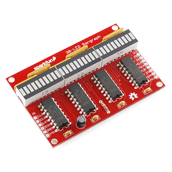
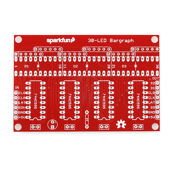
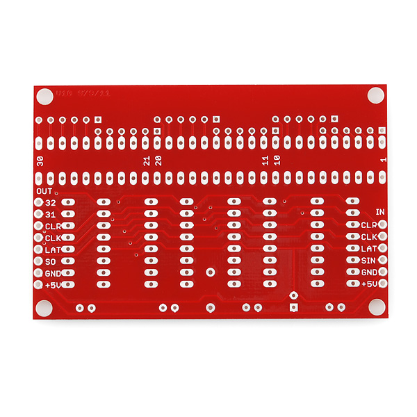
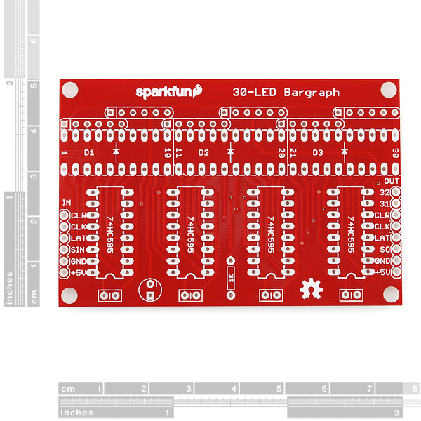
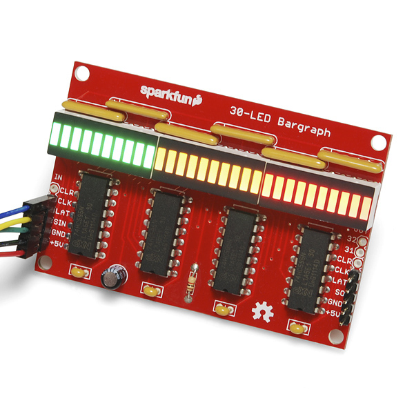
Got too much data for 10 measly segments? This kit contains a PCB and all the parts needed to build a 30-LED bargraph that can be driven by an Arduino or other microcontroller.
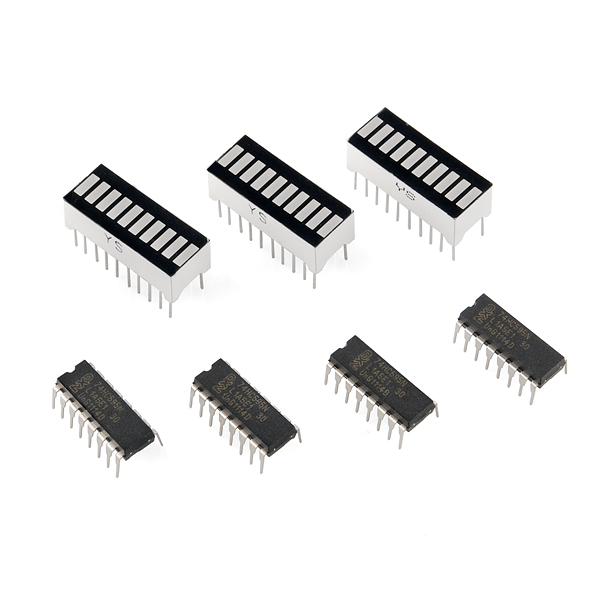
This kit uses our 74HC595 shift registers and 10-Segment bargraph modules to create the display. We supply one green, one yellow, and one red module for 'safe / caution / DANGER!' displays. The display is easily driven by a microcontroller using an SSI interface, and you have individual control over every LED.
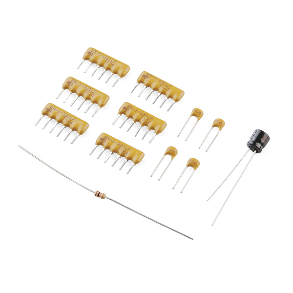
Note: This kit comes unassembled and requires basic soldering skills. The included resistors may vary in color depending on our supplier.
Note: The pinout on these bar graphs may vary from what is listed on the datasheet. Before soldering your kit into place, we recommend testing the polarity on the LED bar graph to confirm its orientation.
- Requires 5V at 250mA max (all LEDs on)
- Synchronous Serial Interface (SSI)
- End-stackable to create larger displays
- 3" x 2"
- [Schematic](http://cdn.sparkfun.com/datasheets/BreakoutBoards/Bargraph Breakout v10.pdf)
- [Eagle files](http://cdn.sparkfun.com/datasheets/BreakoutBoards/Bargraph Breakout v10.zip)
- Datasheet (LEDs)
- Datasheet (74HC595)
- [Kit Guide](http://cdn.sparkfun.com/datasheets/Kits/Bargraph Breakout Kit 111227.pdf)
- GitHub (Design Files & Example Code)
- GitHub (Library)
SparkFun Bar Graph Breakout Kit Product Help and Resources
Core Skill: Soldering
This skill defines how difficult the soldering is on a particular product. It might be a couple simple solder joints, or require special reflow tools.
Skill Level: Rookie - The number of pins increases, and you will have to determine polarity of components and some of the components might be a bit trickier or close together. You might need solder wick or flux.
See all skill levels
Core Skill: Programming
If a board needs code or communicates somehow, you're going to need to know how to program or interface with it. The programming skill is all about communication and code.
Skill Level: Competent - The toolchain for programming is a bit more complex and will examples may not be explicitly provided for you. You will be required to have a fundamental knowledge of programming and be required to provide your own code. You may need to modify existing libraries or code to work with your specific hardware. Sensor and hardware interfaces will be SPI or I2C.
See all skill levels
Core Skill: Electrical Prototyping
If it requires power, you need to know how much, what all the pins do, and how to hook it up. You may need to reference datasheets, schematics, and know the ins and outs of electronics.
Skill Level: Competent - You will be required to reference a datasheet or schematic to know how to use a component. Your knowledge of a datasheet will only require basic features like power requirements, pinouts, or communications type. Also, you may need a power supply that?s greater than 12V or more than 1A worth of current.
See all skill levels
Comments
Looking for answers to technical questions?
We welcome your comments and suggestions below. However, if you are looking for solutions to technical questions please see our Technical Assistance page.
Customer Reviews
4.3 out of 5
Based on 3 ratings:
1 of 1 found this helpful:
Easy way to experiment with Serial to Parallel Converters
The board arrived pretty quick. Assembly is very simple. I used the picture to orient the parts, and guess what - the way the LED block is shown in the picture with YS facing the IC's is incorrect. I learnt it the hard way and had to desolder the 3 LED blocks and remount them. Desoldering showed me that the quality of the PCB is pretty good. However if I were to do it again, I would assembly only one 74HC595 and one LED block. Then check it at that point. If all worked well, i would assemble the rest. The purpose of me getting the board was use 4 DIO ports on a Keithley 2400 power supply to control 128 relays. I used DIO#1 for CLR, DIO#2 for CLK, DIO#3 for LATCH and DIO#4 for SIN. This board gives me a visual if I will be setting the relays correctly. Now that the HW is all good, I can focus on the SW development & extend the concept to 128 individual controls.
This kit arrived in a timely manner, no delay, like that. Actually read the installation document before its arrival, and it's a well written and well illustrated paper, I really learn a lot from it. If you follow the procedures, as I did, and don't skip any step, you'll be rewarded with first-time power-up success. It works for me 100% Overall, this kit is well built and the PCB is supra. Oh, I had a great time putting it together. You got one happy camper here.
Das Blinkenlights!
Despite some initial confusion about manufacturer-mispackaged bargraph LED arrays (and having to replace one,) got this breadboarded and up and running with the example sketch. Fantastic results! Now to find a use for it grin 10/10 will buy more parts to build more circuits along these lines
RETIRED?!?! You make me sad, Sparkfun. I always wanted one of these and never had the money line up with the memory.
Oh well. Maybe I can make a perfboard version someday... not that that's any real substitute.
Sorry... All the parts should be fairly accessible and the board files are on the page. You can definitely get your own PCBs made, but we no longer carry the kit.
-------------------- Tech Support Tips/Troubleshooting/Common Issues --------------------
LED Bar Graph Polarity Test
You can check the polarity of the LED using a multimeter as illustrated in this tutorial => [ https://learn.sparkfun.com/tutorials/polarity/diode-and-led-polarity ]. The correct orientation of the LED bar graph can be determined by matching the cathode to the silkscreen cathode of the PCB and the anode to the anode side after testing the polarity.
I built one of these last night, and I'd recommend it as a first or second soldering project for the following reasons:
* There's not too much that can go wrong if you follow the directions.
* You end up with a fun board that's easy to connect to an Arduino.
* Soldering multiple similar parts (6 resistor packs, 4 shift registers, 4 caps, 3 bar graph LEDs) makes for good practice.
* Project size is very manageable. Can be completed easily in a short evening by a beginner.
* If you don't follow the directions carefully and, say, install the resistor packs backward, you get a bonus lesson in desoldering!
Nice little kit. (By the way, I don't see it mentioned in your Kits section.)
Agreed on all counts. It's a fun and satisfying kit to assemble. It's also downright handy - I bought it on a whim and ended up being pleasantly surprised at how many things can benefit from a 30-segment readout! Great for visualizing all the things that show up on analog pins.
Easy kit to build, using a magnifying glass lamp - the kind with a circular fluorescent light made identifying the 'beveled' edge of the segmented LED's easy, the bussed resistors --well, I had to verify those with a hand held volt/ohm meter where the Pin 1 location was, after that all went together 1st time with no hitches...which is usually the case, because I am awesome (just seeing if anyone actually reads these posts here)...BTW- anyone know where there are perhaps follow-up projects with these bar-graphed segmented LED's ? where I could build something akin to an evil scientist, cool LED thingy ??
I feel like I order the Spark Fun kits and other assorted items, I build them and then..well they just sit there, so I order another item(s)....and just keep building things, but using existing code that someone else coded -= well I need to become more proficient at writing code that actually works and does something. Is there a consensus of what the 'best' book is out there for making amazing LED Arduino things ??
What I really want to do is this - use this segmented LED bar graph to show the kW and Volts from a Modbus power meter, and heck...I have been working on making such said item and it's been not easy. Anyone know where I can post a 'contract' job to pay someone to take my idea and make it happen ? I will pay them decently for the work to be done.
Cheers, Merlin
We generally recommend folks check out Rugged Circuits for custom work, or with their local hackerspace.
In other words we try to read the comments fairly quickly :)
Why 330 Ohm resistors? That's 9.1 mA / LED. Why not 150 Ohm - are these bargraphs too bright at 20 mA? Or is it because of the shift registers (8 x 20 = 160 mA)?
If you're looking at LEDs for information rather than illumination, you don't want them blindingly bright. These are efficient LEDs so they're plenty bright at 10mA, even outdoors.
Good point, haven't thought about that. Thanks for answering!
how about the same with just one bar graph?
Every shift register has 8 outputs. The bars have 10 inputs. So I wonder why not 4 bars and 5 shift registers? (4x10=40, 5x8=40)
Now there are 3 bars with 4 shift registers (3x10=30, 4x8=32) so 2 outputs can't be used.
We considered larger (and smaller) sizes, but given the hot dog and bun problem, 3 modules / 30 LEDs with two outputs left over seemed like the best cost/benefit compromise. If it helps, we did break out those two extra outputs...
As a technician, I still think it could be a bit (or actually 8-bits) better, but I totally understand the commercial part of cost/benefit :-)
I also see this as a good thing, you could have a ultra high power leds added for a warning. don't worry, there is always going to be that guy that wants it diferent. AND i hate hot dog vs bun. but a 10bit shift register would be silly. Though an 8 bit bargraph would be more than handy...
So, being a complete noob when it comes to electronics ;)
Could I use this kit, but instead of using the supplied 10 segment modules, connect set 4 regular leds per +/- pin combo to build and control a custom led bar?
Indeed you could - just make sure you've got the anode/cathode the right way around.
There is one caveat: The board does not use individual resistors, but rather a resistor network component to effectively give each individual LED segment its own 330Ω resistor. So if you had a red LED with a Vf of 2.2V and a blue LED with a Vf of 3.0V, with similar output characteristics, the blue LED would actually appear a fair bit more dim.
Depending on your application, that may not be an issue, could be worked around by trying to PWM, or dodgily replacing the resistor networks with individual resistors (small 1/8W ones, say).
I finally got around to putting this together but the Kit Guide and library links seems to be broken. Can these files be found in another location?
The links are working fine on this end. Try opening them from another browser if that's possible.
Yep they are working now, weird. Thanks.
I want to make it a battery power indicator. Anyone has the arduino code for it.
Hello! What if i want to use a COMMON ANODE display using this code? What parameters have i to alter in the library?? Thanks
The only change in the code will be that the data needs to be inverted; a '1' sent to the shift register will turn an LED off, and a '0' will turn an LED on. If you're using the "paint" commands, you can get away with altering your sketch to send '0's to turn LEDs on. If you want to use the bargraph function, you'll need to alter the library to flip all the bits before sending them to the shift registers.
Thanks a lot for your immediate response! I now the fact that the bits had to be inverted. The problem is that i am facing some difficulties with the code! (newbie unfortunately). A simple example with bargraph function will be much appreciated!! Thanks again!
The easiest way to solve all these problems is probably to modify the library. Go into your Arduino/libraries/SFEbarGraph folder and edit the SFEbarGraph.cpp file. Change line 226 from:
to:
The '~' will flip all the bits in the output transfer from 1 to 0 and vice-versa.
It works just fine!! Thanks again!! I will comment line 226 for the case of a common anode display! Thanks to you i now know! Another thing is how it will be possible (in the case of the peak detector) to make the 'peak' LED stay lit for some longer time, for example 1 or 2 seconds!
Thanks again for your precious help! I will try that soon!!!
this is a very nice soldering startup - i ordered a kit more already. i would like to know if it would be posible to drive something else with the board other than the barograph led`s ? if for instance i wanted to trigger a mosfet, a relay or a triac would that be posible ? we would like to build an scaled-up version of the bar-graph using regular light bulbs or halogen spots instead of the bargraph-led´s
You sure can! The outputs of the shift registers are standard logic signals (on = VCC, off = ground) that you can connect to anything that will accept such a signal, like a solid-state relay. Let us know what you come up with!
Hi, I have built and tested 8 of these. I have them all in a daisy chain on my mega adk 2560 r3 and tested with the example code. Now here's what I would like to know. I there anyone with some examples of these in a chain, with some sensors?
Neat! We've never tried that many; how did it all work? (And send us pictures when you do something amazing with them!)
I'm not sure if the company notices this. But the resistor packs included in the kit are of a different color as per the pictures in page above and in the kit guide.
Instead of a yellow resistor pack with a dot to indicate which direction to insert before soldering, there is a black resistor pack with a dull yellow line on 1 end. I'm going to assume that is the correct orientation.
Also, the kit guide's tips suggested soldering 1 pin first to "hold" the part in place. But what it doesn't say is how to solder smaller multi-pin parts like the shift registers or the resistor packs which do not have a flat surface to rest the part on. Had to figure out my own way to do it.
Thanks for pointing out the component change :) Yes, the line probably indicates pin 1. If in doubt, a multimeter should provide the answer.
As far as soldering goes, it depends a bit on the parts.
Usually the idea is to work from the short components up to the tall components. So tiny diodes tend to go first, followed by resistors, ceramic caps and transistors, ICs, electrolytic caps and any really big stuff. That way there isn't really any need for something to hold them in place as just placing the board upsidedown on a flat service will have the desired effect.
Resistor networks can be a more difficult beast due to their odd shape and typically short legs. I usually bend the first and the last pins a tiny bit outward (same as you might with a single resistor). That keeps it from falling out, at least. You can then just solder the pins in any order you like.
Other parts - well, tape can be a godsend :)
Well, I got it all put together but when I run the example code, only the center bargraph lights up (i.e. the yellow one). Any thoughts as to what I may haved done wrong?
Might it be possible that you inserted the outer two bar graphs, or their associated resistor networks, the wrong way around?
There's several other possible causes, but since the middle one does light up, at least the driver ICs up to and including those used for the middle bar graph should be working fine and track damage seems unlikely.
Yes, dang it. That is precisely what I did. The beveled edge - marking pin 1 - is exactly 180 degrees off from where it should be on the 1st and 3rd bargraphs. Even though I'm clearly an amatuer, I'm feeling so much more so now. All the more so because I spent quite a while figuring out how pin 1 was marked - even took about 10 minutes to show my wife the beveled edge.
Well, I'm going to be getting more practice with my solder sucker. Thanks for pointing out the obvious. I had all 3 bargraphs correctly oriented prior to showing them to my wife :) and my intent was to solder just 1-2 pins on each one just to ensure this didn't happen. The best laid plans of mice and novices...
The funniest thing... I was so proud of my soldering job on the bargraphs as well - bettter than anything prior... nearly perfect litttle volcanos with not too much solder, no globs, drops or smears... only on each pin 2-3 seconds. Ah well, I guess that is why they call it learning.
Thank you, Kamiquasi. I was so confident I'd done it right that I didn't even bother to double check until you suggested the possibility....
Well that's certainly one nice thing about this board - it's easy to practice soldering on (somebody way up in the comments mentioned the same, and sounds like you made some fine solder joints indeed!).. and, of course, de-soldering.
At least you'll be glad to know that it's unlikely that you managed to liberate the magic smoke on those bar graphs :) ( Or maybe that counts toward disappointment.. hmmm )
Once it's up and running, have fun! It's amazing how entertaining this can be (cobbled one together on breadboard) once you get into the individual addressing capabilities.
My wife already thinks I'm crazy... what with the solder guns and the resistors and capacitors. And the books. She reminds me that I'm a software engineer. I tell her that it is never too late to ride a wave... or a waveform for that matter. But the last time I was this certain a new trend mattered was when I saw the very first graphical web browser
You did mention they were oriented the right way around before you showed your wife, then the wrong way around afterward. Now, I'm not saying she sabotaged it, but it is interesting, isn't it? ( Yes, I'm kidding Mrs. Magic Smoke! )
Hardware and software are actually not all that different, especially when doing digital - and it's certainly possible to write code the wrong way around, too ;)
Hello amigos... Can someone help me understand the purpose of the 5 capacitors? Is it some sort of safety feature to protect the IC or LEDs? Thanks!
They're "decoupling capacitors", there to handle the power surges that can result from turning lots of LEDs on and off, which could otherwise sneak into the power supplies of the chips causing them to behave erratically.
Thanks! The more I've read that makes perfect sense!
Th capacitors are to make sure that the power isn't surged; it just makes sure that you don't throw in too much voltage/current, and can also remove small fluctuations that may occur in the voltage/current when you plug in the source.
Can you use an IC port to make the LED's modular?
IC sockets? Of course. The pins on the LED bargraphs are the same spacing as a standard 0.3" wide DIP IC. You could also use longer female headers, in either standard or machine-pin.
Hi i've mounted the board and i've hooked it up to my arduino duemilanove, i've downloaded the library i tried the example with the library but it gave me an error " 'class SFEbarGraph' has no menber named 'begin'. do you know what could be the problem? However the example without the library works! I really can't understand why. Can you please help me. thanks
Does the library and examples show up within the Arduino IDE menus? (e.g., this menu item should exist: File/Examples/SFEbarGraph/bargraph_example). If yes, the library is probably installed correctly. If no, Arduino can't find the library. Put the library in a folder called "libraries" within your sketch folder, and restart the IDE.
Also, are you using Arduino 1.0 or later? The library was written for Arduino 1.0.
the library is installed correctly and I use an Arduino 1.0.1 but it still doesn't works. maybe the cause of the problem is that I'm using an arduino duemilanove? I don't know.
I've re-downloaded the library and the code is different (maybe you've corrected it over time) now it works!!!! really awesome!!!
Great! Glad to hear it works now. We did update the library a while back to fix a few bugs and update it for 1.0. Let us know if you have any other questions or problems, and have fun!
I might get this just because I can't wait for them to restock the red and green bar graphs
I built four of these kits with my little brother (10 yrs) last night. I found it was a great kit to teach him how to solder. We also hooked up a potentiometer and had the graph light up based on the value, he was pretty excited. Thanks Sparkfun!
Easy kit to assemble. Haven't powered it up yet, but it looks really cool once assembled.
One tip: Installing the 2nd and 3rd bargraph displays can be a little tricky since it's a tight fit and there are a lot of pins to line up. I recommend first aligning (but not soldering) the bargraphs to the holes on the other side of the board. Here it is much easier to make sure every pin is aligned. Then, it should be it a little easier to install it on the correct side.
What are the pin connections for the Arduino MEGA rev3 board? I tried 51/52/53 with no luck. I guess it only works with the UNO board I have. I tripled checked the connections and pin no's. It must either be the SPI file or something else. I don't know what I'm missing. I selected the Arduino Mega 2560 board in the Arduino sketch program, maybe there is another board I should select. Help!!
Help is on the way! Which version of the Arduino software are you using?
The 1.0 version. The board programs fine, but the pins must be different or something. I also tried the older version 0022 and got the same results. I also tried different boards (no luck there) I used a OSEPP (uno clone) board, and the bargraph works fine, its just the MEGA i'm having trouble with. Thanks.
Got it, good catch! The bug is that the example code explicitly sets pin 10 to be the LAT signal, ignoring whether we're using a Mega or not. You can fix this by either moving the LAT wire to pin 10, or changing line 58 in the bargraph_example.pde from BG.begin(10,numbargraphs); to BG.begin(); (which will use the default Mega pins), or BG.begin(53,numbargraphs); (if you wish to change the LAT pin or use more than one bargraph).
The libraries also need to be updated for version 1.0, but in the meantime you can change the line #include "WProgram.h" to #include "Arduino.h" in both SFEbarGraph.h and SFEbarGraph.cpp.
Sorry about that, we'll update the code, and thank you for the bug report!
Yep! That's the ticket. I changed line 58 in the example code. Was new to the board scheme and haven't played around with it much yet. Interesting little board, I may add (chain) another one with all blue next. Thanks again !
The 74HC595 object I wrote for the Parallax Propeller should work for this kit. The number of outputs the driver can control - 4 74HC595's / 32 lines is an exact match to the number in this kit, and it will allow you to do PWM on all of them independently.
http://obex.parallax.com/objects/437/
Any chance you can find some bi or tri colour bargraphs like these?
We'd love those too, and we're actively looking for such parts.
I know this is five year old comment, but try this: https://www.digikey.com/product-search/en/optoelectronics/leds-circuit-board-indicators-arrays-light-bars-bar-graphs/524736?k=&pkeyword=&pv37=1841&pv37=1012&pv37=1015&pv37=1879&pv37=1019&pv37=1880&pv37=1471&pv37=1795&pv37=1672&pv37=1798&FV=fff40008%2Cfff801c0%2C33c0297&mnonly=0&newproducts=0&ColumnSort=0&page=1&quantity=0&ptm=0&fid=0&pageSize=500
Also interesting to note is that one of Digi-key's suppliers has curved bargraphs, though, sadly, minimum purchase is a lot of 100, which makes it hard for hobbyists purchase simply to tinker with.
https://www.digikey.com/product-search/en/optoelectronics/leds-circuit-board-indicators-arrays-light-bars-bar-graphs/524736?k=&pkeyword=&pv207=662&FV=fff40008%2Cfff801c0&mnonly=0&newproducts=0&ColumnSort=0&page=1&quantity=0&ptm=0&fid=0&pageSize=500
The manufacturer, Lumex, has a number of color options for this curved packaging type, in both common cathode and discreet cathodes (with discreet cathodes being more expensive.) I'm working with their datasheet to work up a breakout board for these units, on the off-chance I have the opportunity to obtain a number of them.
Is it possible to get just the board?
Sorry, we don't sell the board separately. However, you can use the EAGLE files above to make the exact same board through BatchPCB or the boardhouse of your choice.