- Home
- Product Categories
- Kits
- Multimeter Kit

Multimeter Kit
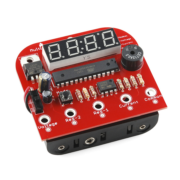
The Multimeter Kit provides you with everything you need to make your own multimeter capable of measuring voltage (0-30VDC, 0.05 resolution) current (0-500mA, 1mA resolution) and resistance (0-100kΩ). The resistance mode also includes a continuity test: the buzzer will sound when the resistance probes are shorted together, this is one of the more handy tools of any multimeter.
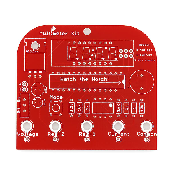
Using the Multimeter Kit is very straightforward. To measure voltage connect your probes to the 'Voltage' and 'Common' pins, for current measurement the 'Current' and 'Common' pins. Resistance measurement uses the 'Res-1' and 'Res-2' pins. The decimal points are used in resistance measurement mode to indicate 10kΩ and 100kΩ ranges.
This kit now includes test probe cables! Batteries, however, are not included. Also, we've changed some footprints to make it easier to assemble without bending components' legs around. The buzzer has been moved from one pin to another as well so this revision does have slightly different firmware from the last.
Note: using the resistance measurement mode on live circuits is not recommended. Also, do not test current or voltage on devices that may be outside the measuring range (no negative voltages or currents)! The multimeter is very simple, and won't replace your Fluke meter, but it works perfectly for simple troubleshooting.
Note: Brought back for only a limited time. We found some remaining stock and decided to make what little we had left available to those who may want it.
Replaces:KIT-10338
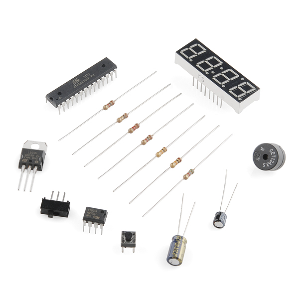
- 1x Multimeter Kit PCB
- 1x ATMega328 programmed for Multimeter Kit
- 1x LM358 Op-Amp
- 1x 3.3V Voltage Regulator
- 1x Red 4-Digit 7-Segment Display
- 1x Buzzer 2.048 KHz
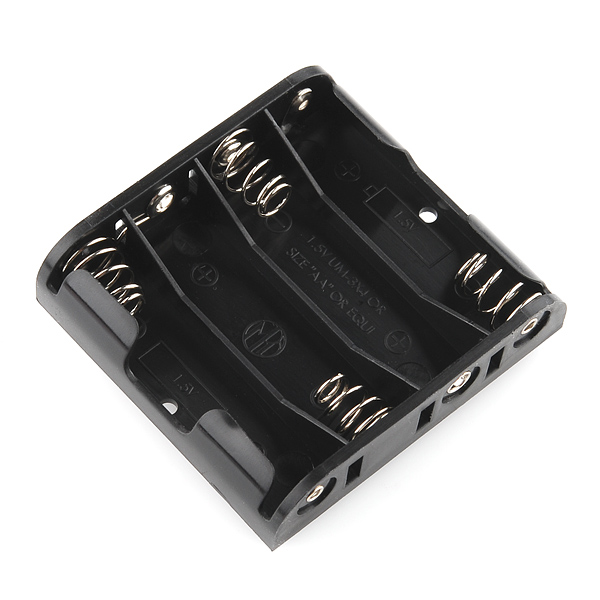
- 1x Battery Holder Pack AA x 4
- 1x 100uF Capacitor
- 1x 10uF Capaciator
- 2x 1.0kΩ Resistor
- 2x 10kΩ Resistor
- 1x 5.6kΩ Resistor
- 1x 1.2kΩ Resistor
- 1x 1.0Ω Resistor
- 1x SPDT Mini Power Switch
- 1x Push Button Switch
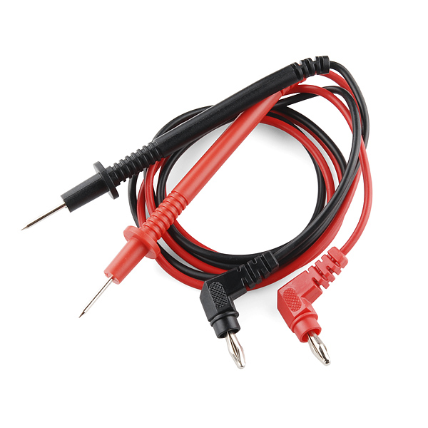
- 1x Banana to Test Probes Pair
- Assembly Instructions
- Schematic
- Eagle Files
- [Source Code](http://cdn.sparkfun.com/datasheets/Kits/Multimeter Kit v18.zip)
- Awesome time-lapse assembly video
Multimeter Kit Product Help and Resources
How to Use a Multimeter
January 9, 2015
Learn the basics of using a multimeter to measure continuity, voltage, resistance and current.
Core Skill: Soldering
This skill defines how difficult the soldering is on a particular product. It might be a couple simple solder joints, or require special reflow tools.
Skill Level: Rookie - The number of pins increases, and you will have to determine polarity of components and some of the components might be a bit trickier or close together. You might need solder wick or flux.
See all skill levels
Core Skill: Electrical Prototyping
If it requires power, you need to know how much, what all the pins do, and how to hook it up. You may need to reference datasheets, schematics, and know the ins and outs of electronics.
Skill Level: Rookie - You may be required to know a bit more about the component, such as orientation, or how to hook it up, in addition to power requirements. You will need to understand polarized components.
See all skill levels
Comments
Looking for answers to technical questions?
We welcome your comments and suggestions below. However, if you are looking for solutions to technical questions please see our Technical Assistance page.
Customer Reviews
No reviews yet.
Might want to update your header-ad, it links to the retired version
Any plans to add a usb port? It would make a great datalogger.....
Interesting idea, another option would be to breakout some pins for connecting an optional SD card reader. There also appears to be vias for 6 pin programming header "hidden" under the LCD, so TX and RX or I2C might already be accessible from the backside of the board.
This kit appears to be designed with through-hole components only. The ATmega32u4 (for a keyboard HID) or FTDI chip (for serial access) are both surface-mount only.
Perhaps you could use this design as a starting point, and submit one with a USB port and/or SD card to BatchPCB!
I was just thinking of adding the SD card reader as a separate board, like this one or that one (and yes I know I'd need additional components if I wanted to do I2C, etc...), wired to the existing kit. Then perhaps putting both in a small enclosure with proper holes.
I am curious why this kit was discontinued. Was it simply a business decision (wasn't popular enough), or was it flawed in some other way?
Expensive, and not a high seller. Besides, it was more fun as a kit than useful as a product (you can get a real multimeter that works a lot better for 1/2 the price). For a beginning soldering kit the Simon is probably way better and more fun when you are done. For a more advanced soldering kit we have plenty of other options.
(Comment "deleted" since it was posted on wrong product.. it was meant for the op-amp tat this product uses.)
The one probe should be plugged into RES-1 (internally connected to +3.3V) and the other into RES-2 (internally connected to RS=1k to GND) and mode 3 selected for resistance measurement. The 'common' is not used as it is connected to GND. In resistance mode the A/D reads the voltage of the divider formed by R (unknown) and RS=1k. My results shows : OK measurements below 30kohm, but higher values suffer in accuracy due to the voltage divider ratio and the limited A/D resolution. e.g. 47k measures 63k, 62k measures 67k, 68k measures 127k. As this is an educational kit, it is of course not fair to compare it with a test instrument grade DMM. Voltage measurements are OK up to +30V DC (no reverse polarity as stated in the description). Current measures OK up to 300mA (the limit is due to the output swing of the LM358. The shunt resistor can anyhow only dissipate 0,25W equal to 500mA for a short while. The project was built by one of our students as part of a summer school project and the student had loads of fun and learned a lot. Thanks Sparkfun.
The source code is already in the uc ATMega?
besides the potential for a good data logger , is this a decent meter? has anyone had any problems with it ? is it accurate ?
It looks like the TX pin on the 328 is unused? It would not be hard to add data logging code that writes to the serial line and hook it up to the RX on an FDTI "friend." Serial logging is a kind of a high-end feature not often found in the $20 or less multimeter.
Assuming, of course, there is some way to shoe-horn in the ISP-6 header pins. It looks like there are traces on the board heading from the ISP pins to the microcontroller? Has anyone reprogrammed their kit this way? ("in service" programming rather than pulling out the (socketed) 328 sticking it in the programmer with a socket?)
Speaking of sockets, it would be a good idea to add a socket for the 328. Only $1 more. (They really should include this in the kit!)
Could someone tell me the dimensions of this product? Thanks!
I'm not sure if it was corrected in this kit but there is an error in the code for voltage mode in the KIT-10338 kit. The calculation gives you the voltage at the AD input and NOT the voltage at the probe. The calculation should multiply by 3.281*1.12/1.2=3.062, not by 3.281. That would fix the voltage error reported by bdodds on the old kit. Basically, the calculation does not factor in the voltage divider (which needs to be scaled by 10X due to the decimal point).
This page does not have a link to the source code, but the retired version does. Please add the link to the source here, as it took me a while to track it down.
Also the supplied (banana) leads don't exactly go into the holes if you mount the board over the battery pack as shown in the photo. They just limply sit there and flop out again. A solution isn't particularly obvious, but I mounted mine off-center so that the leads could go through the holes.
Any idea as to why when set to resistance the display reads "OL" no matter if the probe is in RES-1 or RES-2?
If you have one of your probes connected to common you may need to connect it to RES-2 instead and the red one to RES-1 to measure resistance.