- Home
- Product Categories
- Battery
- SparkFun 5V Step-Up Breakout - NCP1402

SparkFun 5V Step-Up Breakout - NCP1402
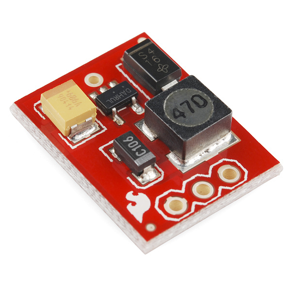
The NCP1402 is a 5V DC-DC converter. This breakout board will accept voltage inputs between 1 and 4 Volts and output a constant, low ripple 5V output capable of sourcing up to 200 mA. This board is great for supplying power to 5V sensors on a 3.3V board, or providing 5V from a AA battery.
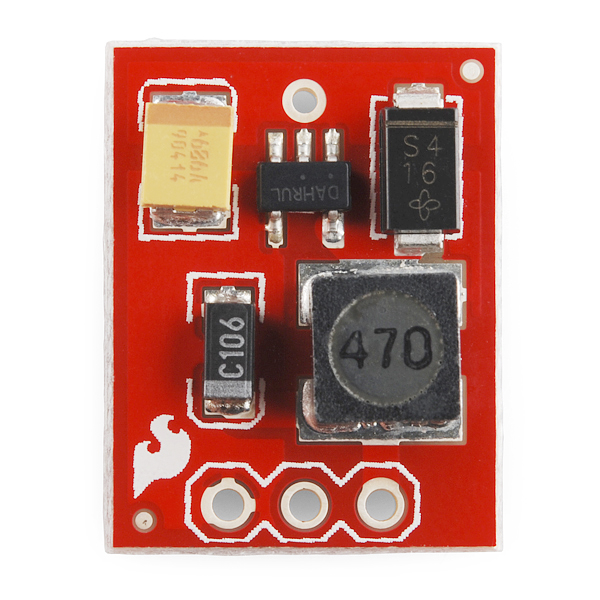
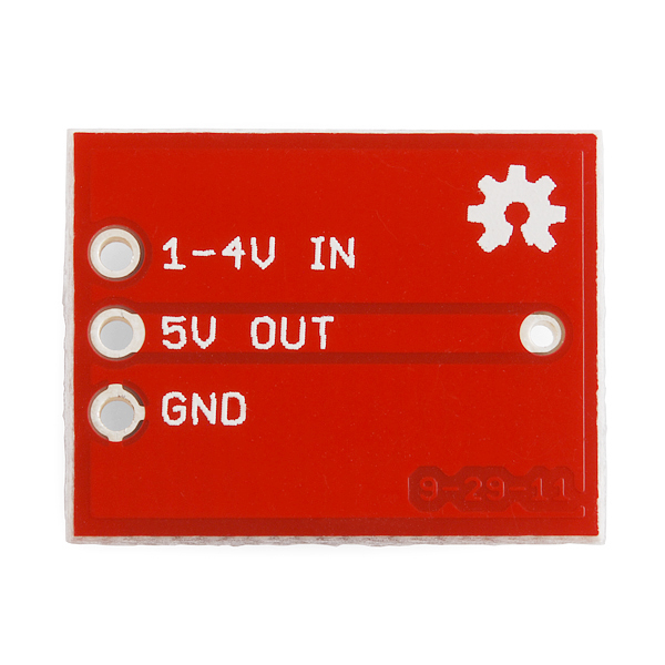
The breakout board includes all of the necessary peripheral components. The input, output and ground pins are broken out on a 0.1" grid to allow easy access on a breadboard.
- Schematic
- Eagle Files
- Datasheet
- GitHub (Design Files)
SparkFun 5V Step-Up Breakout - NCP1402 Product Help and Resources
Core Skill: Soldering
This skill defines how difficult the soldering is on a particular product. It might be a couple simple solder joints, or require special reflow tools.
Skill Level: Rookie - The number of pins increases, and you will have to determine polarity of components and some of the components might be a bit trickier or close together. You might need solder wick or flux.
See all skill levels
Core Skill: Electrical Prototyping
If it requires power, you need to know how much, what all the pins do, and how to hook it up. You may need to reference datasheets, schematics, and know the ins and outs of electronics.
Skill Level: Rookie - You may be required to know a bit more about the component, such as orientation, or how to hook it up, in addition to power requirements. You will need to understand polarized components.
See all skill levels
Comments
Looking for answers to technical questions?
We welcome your comments and suggestions below. However, if you are looking for solutions to technical questions please see our Technical Assistance page.
Customer Reviews
4.6 out of 5
Based on 11 ratings:
1 of 1 found this helpful:
Excellent product!
Works as advertised. The performance is excellent and I've saved an average of $5 from other comparable products.
1 of 1 found this helpful:
Pretty good to have...
If you're developing on a project where the power supplied is only in the 3V realm this nifty little break will get you that power that you're after. However, note it's good for up to 200mA (10 5V LEDs @ 20mA each for example).
3 of 4 found this helpful:
Worked like a charm
The board was shipped fast, worked perfectly, in excellent condition. You rock sparkfun!
1 of 2 found this helpful:
Does exactly what it has to
It takes a smaller voltage and turns it into ~5 volts. My unit's output is about 10 millivolts high, but that's just fine for any project you'd use an off-the-shelf part for.
Only other thing of note is that this thing can take the heat - it's been soldered and desoldered 5ish times now and it still works the same.
This product was mauled when soldering and still worked like a charm anyone who wants an outstanding product buy this
does it's thing
1 AAA or AA battery and you got yer 5 volts. I will be incorporating this design into many mobile projects. I wish the individual components were available separately or as a kit without the PCB.
Nice little board
Shipped fast, works great.
High quality product.
All I bought are working fine. No issues.
thanks
0 of 1 found this helpful:
It works
It is
0 of 1 found this helpful:
It works
It is
-------------------- Tech Support Tips/Troubleshooting/Common Issues --------------------
Coin Cell?
I tested the step up converter – NCP1402 [ https://www.sparkfun.com/products/10968 ] with a coin cell battery. The coin cell was not able to power a 5V Arduino. This would probably be the same for other boost converters. The output power of the coin cell is probably be too low to be boosted for the boost converters. You would need a battery that is able to output more power. It would be better with a LiPo battery with nominal 3.7V.
Also it would sure be nice if the Vin and GND pins were next to each other so a JST connector could be mounted to receive a LiPo battery.
I fail to understand why Sparkfun never seems to breakout the shutdown pin on any of their breakout boards! Why do I have to cut a trace and solder a jumper wire on and SMD part to get it?
That's a fair complaint, sorry about that! We do try to design our products to walk the line between requiring minimum effort to just work out of the (red) box, and being completely spread out and hackable. We don't always get the line right. I have personally have run into identical situations to yours, so I feel your pain! We are trying to be better about breaking out every useful pin while also providing e.g. pullup resistors so that you don't necessarily have to drive that pin to get the circuit to work. We'll see if we can get that pin broken out on a future revision. Thanks for your feedback!
I see that there has been provision for a 0.1" header, but there is only one GND pin. So If I want to add a jst connector for my 3.3v lipo input, there is no GND pin for my 5v output connector. Perhaps add another gnd pin? 1-4Vin GND GND 5V
I have a question. Can this safely be connected to the load pins on a sunny buddy without destroying the sunny buddy board or the battery if the battery is 3.7v?
will this work with the electric imp! the other 5v dc-dc step up would not
What exactly is the point of a "breakout board" if only the bare-minimum pins are broken out? Would really love to be able to enable/disable this using the Chip Enable pin...
On the subject of the shut down CE pin of the NCP 1402. I cut the trace to the pin and attached a jumper wire. When I connect the jumper to ground, the output drops from 5v to around 3.7v with a load, it won't go to 0v. This happens with both breakout board I have. Does anybody else have this problem or a solution?
Ok, I have limited electronic skills, but have a project I'm trying to get dialed in: I have a wind-powered generator that I want to power some LEDs. The issue is that my RPM has to be so high to get the lights to work. I have rewound the generator until I am out of room for wire, and my propeller design limits the available RPM. With a strong wind it works, but I'd like the lights to come on with a more subtle wind. (I have an adjustable voltage regulator to prevent over powering the LEDs in a gale-force wind). The light system wants 4-6 volts, and 30mA. My question is whether this unit or your "Li-power boost converter" would be good solutions to get my lights to come on at lower generator RPMs.
Do the LEDs have to run off the wind turbine? If you are only trying to see when the wind is blowing you, could use the power coming off the turbine to flip a relay or even set it up to light up more LEDs according to how much voltage (speed) is coming from it. This would allow you to power the LEDs from another source, such as a battery.
can i use two of this module to get a dual supply? i.e. -5v, gnd, 5v with a single 3.7v li-ion battery? Please it is urgent
Hi, I am using this module with 3.7V Li-ion single Cell, My doubt is that does it have undervoltage protection or something so when my battery runs below 2.5V the NCP will shut it down. Is it possible ? Is there any other way possible to achieve this ?
Hi, I'm trying to connect a 3.7 input provided by a Lipo-Battery that passes through a P Mosfet. However, when the stepup is connected this input voltage falls to 0.7, what can I do to fix this issue??
I imagine it's due to the way you set up your circuit, do you have a schematic we could look at?
Does the 2000 mah li-po work with this?
Yes, as long as it's single cell so the voltage output is ~3.7V. PRT-08483 will work with this.
MORE CURRENT!!
Come on SF, throw us a bone. Give us something we can put between a 3.7v 2Ah LiPo cell and our Raspberry PIs, beaglebones, etc. I'm willing to pay for it, it just doesn't exist.
Is it possible to use two of this board in parallel to get twice the max output power?
I think aeroguy was mistaken. I'm pretty sure this chip acts as a power source. Putting them in parallel wont do anything to the voltage, but it should give you double the power. If each could output 150mA at 5V if Vin is 3V (let's pretend), then two of them in parallel could provide 300mA total. If current doubles, power doubles (assuming constant voltage).
No, it's not a battery.
I'm just wondering if there is way to increase the mA beyond 200 to say 500 mA?
Not with this board. Infact, you might get 200mA only if Vin=2V and Vout=3V. I recommend planning for lower current (~150mA).
The schematic for this and the 3.3V version are identical. What actually differentiates the output voltage? I have the 5V version and was wondering what I'd have to change on it to get it to output 3.3V?
Unfortunately, you would have to replace the NCP1402 itself. It's not a configurable device - ONSemi produces them in fixed output voltages; NCP1402: 200 mA PFM Micropower Boost Converter
If you wanted something more configurable, check out the LiPower - Boost Converter
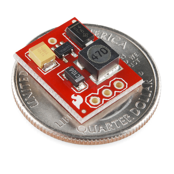
What size is it? (mm)
Since i have mine sitting here, its just shy of the 4mm mark :)
It is 12.7mm (0.5") by 16.51mm (0.65").
The height is a bit more difficult - the tallest component is the inductor, but I don't know which one that is to check a datasheet on, but since the package outline on the board is about 6mm on the long side and the photo is fairly orthographic, after some pixel measuring I'd say it's under 2.5mm tall. Add to that the PCB's thickness itself, do some arbitrary upward rounding, and assume that's 4mm maximum.
Can any one please tell me whether i can connect two of these boards in series to get a 10V output from 2 3.7V batteries? Actually my work is to measure the individual voltage difference of each Li-Po cell with a ADC. I am using a microchip adc which uses the VDD as Vref. So i need a voltage higher than the cell to convert it. Therefore i use this converter to step up the voltage to 5V. It works completely fine when i connect two cells seperately. But when i connect it in series and connect the ADC to output the lower boost converter produces an output of 8V instead of 5V. Guys pls help me.
I did this recently, to test the voltage drain rates of AA cells vs lipo cells with my teensy, and used a software fix. just connect the battery positive to your adc line, and in software multiply the reading by ADC-resolution/5V, in my case a 12 bit ADC i use 1024/5V. reading is typically within 0.05V of my DMM.
The efficiency of this thing is no where near the datasheet efficiency.
Running it on 3 AA batteries putting out around 4.5 volts, this thing increased the current used by my teensy from 10ma to 70ma (vs running the teensy directly on the 4.5v).
I wanted to use this thing in order to get more life out of my batteries, but drawing an extra 60ma completely negates any possible benefit.
You obviously did not read the other posts. You can not run this at 4.5 volts. It will not regulate and will draw more current.
What happens if the input voltage is higher than 4 Volts? It would be really nice to use this with a single cell LiPo or Li Ion battery. But both these battery types have a voltage higher than 4 Volts when fully charged.
It would be nice to know if a 4.2V Lithium rechargable would work with this.
I see a single cell LiPo listed in the "Related Products". I think listing a LiPo implies it would work with this regulator.
According to the posts on the Sparkfun NCP1400 step up board, AND the datasheet, the IC has a max input voltage of 5.5V, so it will work just fine with a fully charged 4.2V lipo or li-ion cell.
The previous posts are incorrect. They are correct in that the I/O pins are rated for 5.5V (or 6V, in the "Absolute Maximum" section, but it's generally best to limit it to normal operating values; ignore the 'absolute maximum' section on most datasheets if you want to play it safe). However, it will not function properly when the input voltage is higher than 4 Volts.
Check out the schematic: The output is connected to the input through an inductor and a diode. There is no way for the device to regulate the output voltage down; it's only passed through the forward-biased diode. That would allow you to use about 5.5V as an input to get out 5.0V, but the part will not be actively "regulating"; sufficiently low output current would cause this to rise depending on the diode's behavior.
Over 4V, you're not using the regulator as intended. You won't damage this device, but your noise levels and load regulation won't be as good. That's probably OK; Lithium batteries only have a brief period at their fully charged state during which they're over 4V.
noise levels? 10 microfarad capacitor :)
Would this arrangement (Lipo/ion straight to boost converter) endanger the cell? Or is the under voltage protection on the cell sufficient to prevent dangerous discharge? Apologies for going slightly off topic.
Thanks, Andrew
Just have a look at the datasheet, up to 6V is allowed. I do not find any information what will happen if the input voltage is higher than the output voltage but 4.2V should be no problem.