- Home
- Product Categories
- Arduino Shields
- Go-Between Shield

Go-Between Shield
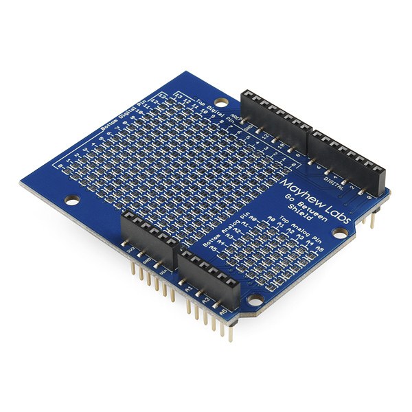
You hear it all the time in the Arduino community, "will this shield work with my other shield?." I think we've all been disappointed to find that two of our favorite shields compete for control of a digital pin here or a serial pin there. While there are sometimes some clever workarounds from elegant code modifications to aggressive 'greenwiring,' Mayhew Labs may have come up with the simplest solution thus far: The Go-Between Shield.
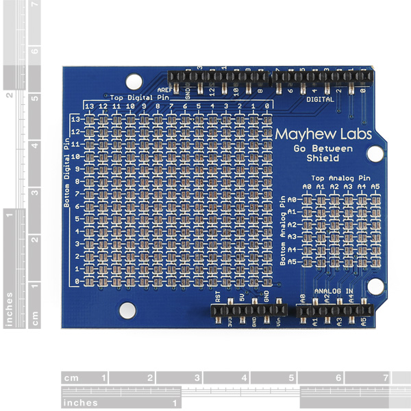
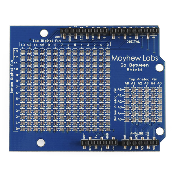
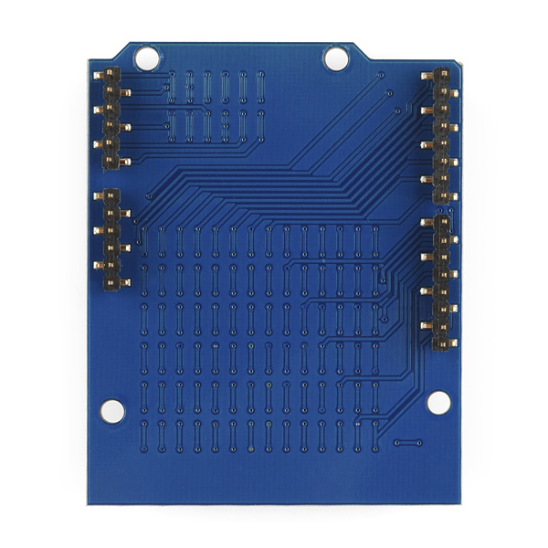
The Go-Between Shield "goes between" two shields that aren't compatible and effectively reassigns the pins. This trickery is achieved by isolating the top and bottom sides of the shield with surface mount headers and breaking them out into tables of jumpers that can be bridged to divert signals to and from different pins. For instance: If you have two shields that require use of pin A1, you can simply close the correct jumper and stack the Go-Between shield between the two conflicting shields. Now the shield above the Go-Between will think it's using A1 when in reality it's connected to the Arduino's A0. Now your shields aren't stepping on each others' feet, so to speak.
The Go-Between Shield is also a solution to some shield compatibility problems with Arduino clones such as the Maple or Netduino.
Go-Between Shield Product Help and Resources
Core Skill: Soldering
This skill defines how difficult the soldering is on a particular product. It might be a couple simple solder joints, or require special reflow tools.
Skill Level: Rookie - The number of pins increases, and you will have to determine polarity of components and some of the components might be a bit trickier or close together. You might need solder wick or flux.
See all skill levels
Core Skill: Electrical Prototyping
If it requires power, you need to know how much, what all the pins do, and how to hook it up. You may need to reference datasheets, schematics, and know the ins and outs of electronics.
Skill Level: Rookie - You may be required to know a bit more about the component, such as orientation, or how to hook it up, in addition to power requirements. You will need to understand polarized components.
See all skill levels
Comments
Looking for answers to technical questions?
We welcome your comments and suggestions below. However, if you are looking for solutions to technical questions please see our Technical Assistance page.
Customer Reviews
No reviews yet.
This is amazingly simple and elegant. I want to high five whoever thought this up.
I owe the person who invented this a drink - hope they get rich beyond their wildest dreams. Elegant and clever!
I second that motion - let's buy handfuls of these to make that a reality!
This is a really awesome idea!
Clever!
Wouldn't it be simpler to have shields with jumpers to configure pins? Similar to how SoundCards used to have jumpers to set the address, IRQ and DMA?
Simpler to adjust yes, but far, far more expensive, you need 14^2 + 6^2 = 232 header pin pairs, and someone needs to attach all of them to the board...
I didn't mean to configure the pins directly, but using SPI (using a 74HC595 or similar) with address decoding for the select line.
That way you could have a huge number of shields and configure the SPI select line via, say, only four or height jumpers (16 to 256 different shields). By also using SPI to set the select line, you could do both the addressing and data transfers with only one SPI port on the microcontroller.
Or maybe two SPI ports, one for the address and one for the data so you don't waste time sending the address every time you want to send a byte.
If everyone would standardize on that, it would be as easy to configure the software as the hardware (i.e. which port is your shield configured to?).
If someone started a new standard with this idea, it would also be a chance to fix the non-standard spacing as well, since SPI and power lines would require a lot less pins anyway. Just put the connectors/pins on the corners of the shields for strength and stability.
Or maybe a new type of shield, compatible with the current ones, that only uses the idea with the two SPI ports and just connects the pins it doesn't use for the other, older shields?
Or they could just have two sets of female headers, and you supply your own wire. I really don't see why most shields don't do this, since they just need a hole (they don't need to supply the headers, since it's an "advanced" feature) and a "default" trace that you can cut.
Great companion website for this shield.
Thank you for the site!
Thanks, thats an epic list. I love the massive stack of shields they show.
have i heard of you before? (Adafruit's weekly ask an engineer)
So, if I use this between an Arduino Motor Shield and an Adafruit GPS Logger shield which both use pins 11, 12, and 13. What do I have to do besides make the appropriate solder connections and reassign pins in the code when I declare my constants?
Is there something "special" about these particular pins. I was told I would have to use a sofware SPI library because they are "Hardware SPI Pins."
If those shields are using pins 11,12, and 13 for SPI they you do NOT want to reroute them. SPI is a bus designed to communicate to more than one device (controlled by the CS pin). You can not reroute the pins and still use the SPI library. Software SPI is similar to software serial but less popular (because SPI is designed to have more than one device on it). Basically it lets you use different pins and mimics the SPI bus in software. This tends to be complicated and processor intensive, but if you do need it you should be able to find a software SPI library out there.
I went to the Arduino website and looked at the Mega 2560 info. Their page says the SPI pins are:
SPI: 50 (MISO), 51 (MOSI), 52 (SCK), 53 (SS).
So does this mean I don't need to mess with a Software SPI library? I'm confused.
The SPI pins on the Uno or any ATMega328 based uno are on pins 11,12,and 13. On the Mega2560 they are on 50,51,52 (SS is the same as CS and is not really part of the bus, but a pin unique to each SPI device to control which one is talking at any given time). As a general rule I don't see any reason you would ever need to use a software SPI library. I'm sure there are instances, but you should be able to run all SPI devices on the one bus.
OK. So I'm good to use the go-between and just modify my pin assignments then?
I'm not familiar with Adafruit's board and am not sure which motor driver shield you are using so I can't say for sure, but most likely.
Its a nice and simple idea! BUT i am worried about noise/interference has it been tested for any of this? or at least SPI speeds?
The next version should support A6 & A7 from the Seeeduino since those give two more pins to work with.
I could have sworn that there were 80 of these a few days ago. They sold fast!
A version of this board that does all the pins for the Mega would be very welcome. For instance, it would be great to be able to reroute the TX and RX pins of the cellular shield to hardware UART pins that exist on the Mega but don't exist on the Uno without having to cut the pins and use jumpers like I do now.
Also a version that encompassed a screw shield would be really useful, again especially if it supported the Mega. (A screw shield for the Mega would also be great.)
Yes, a version of this that supported the mega, or even better the seedstudio version of the mega would be awesome. biggest problem I have had is serial port contention. the simple ability to re assign serial ports would rock! actually a version of this board that had screw terminals on 1 side and pins on the other would rock too, mucho help with greenwire mods. just don't connect the 2 sides but allow use of wire to jumper between.
This is what I have been looking for!