- Home
- Product Categories
- Current
- Non-Invasive Current Sensor - 30A

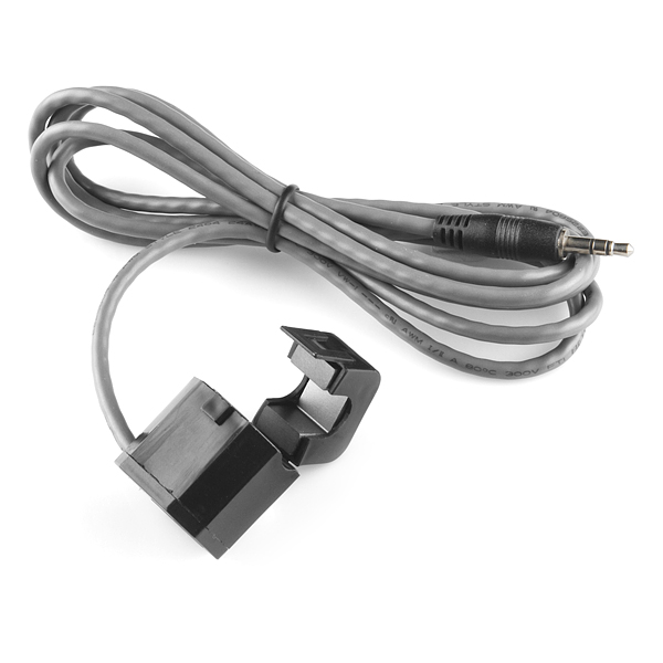
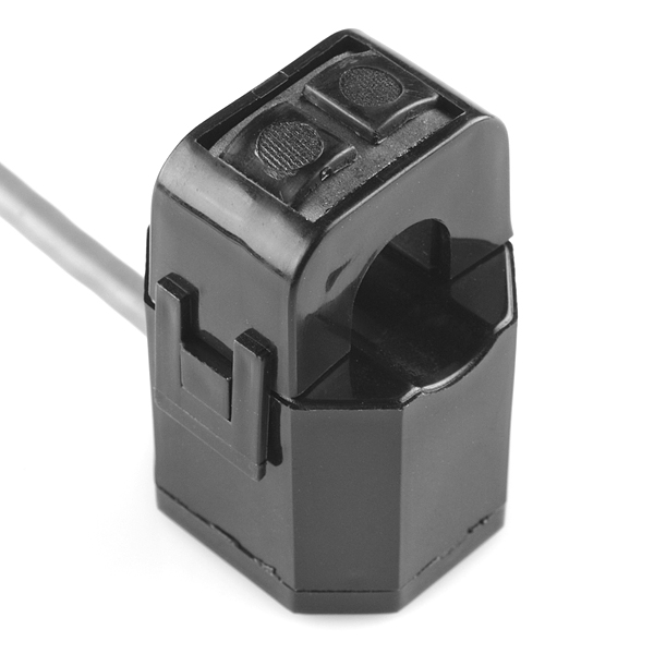
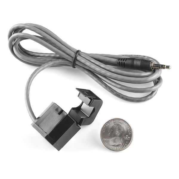
This non-invasive current sensor (also known as a "split core current transformer") can be clamped around the supply line of an electrical load to tell you how much current is passing through it. It does this by acting as an inductor and responding to the magnetic field around a current-carrying conductor. By reading the amount of current being produced by the coil, you can calculate how much current is passing through the conductor.
This particular current sensor will measure a load up to 30 Amps which makes it great for building your own energy monitor to keep your power usage down, or even building an over-current protection device for an AC load. This sensor does not have a load resistor built in, so in most cases it will be necessary to place a resistor across the output to convert the coil's induced current to a very small measurable voltage.
Replaces:SEN-10341
Non-Invasive Current Sensor - 30A Product Help and Resources
Environmental Monitoring with the Tessel 2
October 13, 2016
Build an air-conditioner monitoring device to collect environment information and store it in the cloud.
Additional Example Tutorials
Here’s another Arduino example:
Here’s another example that uses the Particle Photon:
Here's another example that uses the Tessel 2:
2 of 2 found this helpful:
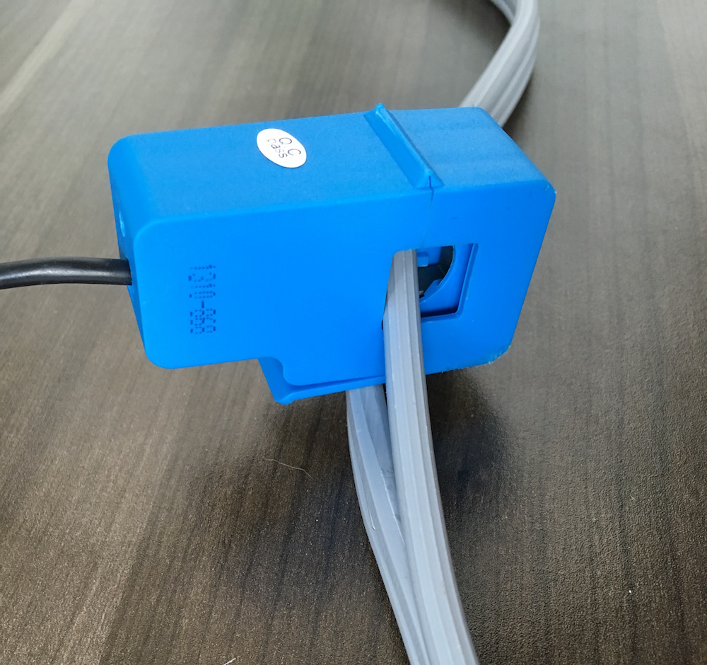
"Modifying" a Cable for Sensing Current
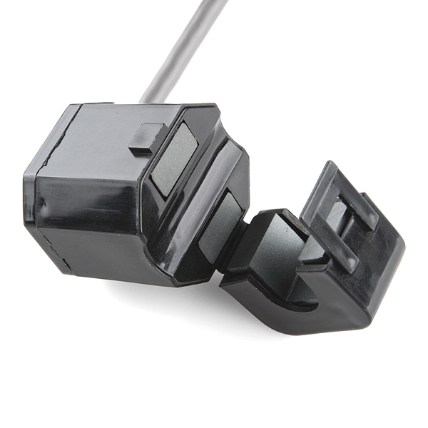
You will not be able to use this sensor if you clamp it around a cable. The wires inside the cable will cancel each other out. If you do not want to modify your primary cable that is connected to you device, try buying an additional extension cord that is rated for the device. Make sure to get an extension cord that you can easily split the wires to access the "hot" or "neutral" wire. You will need to modify the cable like so:
For more information on safely modifying a cable, try looking at this tutorial [ Environmental Monitoring with the Tessel 2 : Build It ].
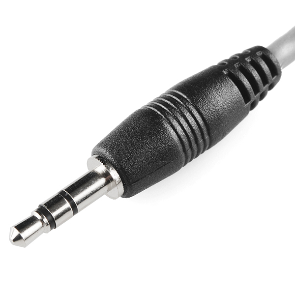
3.5mm jack pinout
Wires are connected to the tip and sleeve of the 1/8" jack. The center conductor on the jack is not connected to anything. To easily connect to the connector, try using the SparkFun TRRS 3.5mm Jack Breakout .
4 of 4 found this helpful:
AC vs. DC
This type of current sensor is for measuring AC current only. They will not work with DC.
Comments
Looking for answers to technical questions?
We welcome your comments and suggestions below. However, if you are looking for solutions to technical questions please see our Technical Assistance page.
Customer Reviews
4 out of 5
Based on 18 ratings:
9 of 9 found this helpful:
Good performance but weak 'hinge'
Installed 2 of these to monitor current to heat pumps. Small size, split core design and long leads make installation easy in the elec panel but the thin plastic that acts as a hinge on the split core looks very weak. I used 'zip' ties to be sure they don't open in the panel years from now.
I am using the cr magnetics design for a 'precision rectifier' to produce amplified DC voltage outputs with a ratio of 20mvdc/1Aac. Our typical 10Aac load produces 200mvdc output, easily monitored with an arduino.
The spec sheet uses a 10ohm load resistor to characterise the output voltage vs current curve. I'm using a 20ohm resistor to double the sensitivity. I ran a load curve and get linear results as with the 10ohm load but at double the sensitivity.
1 of 1 found this helpful:
Works very well. Suprisingly well in fact.
I was surprised at the level of detail I was able to get from this. I'm fascinated by the data I'm collecting. Plan to order quite a few more soon.
4 of 4 found this helpful:
Good little CT
I wrapped 4 turns of my wire through the window of the CT for better accuracy, also found out the Tip and the Sleeve were connected to the CT, not sure what the ring is used for.
4 of 4 found this helpful:
Work great with Raspberry Pi
Using an MCP3002/3004 analog to digital converter, I was able to get this sensor working with a Raspberry Pi. It was accurate to about a tenth of an amp when clipped around the hot wire of a short extension cord. Just what I needed!
https://github.com/commandtab/brewbot
3 of 3 found this helpful:
decent product, needs better documentation
This is a decent current sensor. Alas, there isnt much documentation on it or how to use it. The device has a stereo 1/8" jack (3 connections) but the device only uses 2... Which two? your guess. The referenced "Arduino Energy Monitor Project" references the OpenEnergyMonitor.org ... and their Emon library. Alas the project is for UK and tailored to their boards. The rather important Calibration step is obfuscated for other boards (bit of MagicHappensHere). Maybe when(if?) we finish ours we will correct that.
2 of 2 found this helpful:
Repurposed to sense motor running
This was the most economical solution to my oil burner monitor project. I bought these to log my oil burner motor and circulator on time (not power level) by sensing the current going to the motor. But it occurred to me that I would need to open some electrical boxes to place the current sensor around feed wires. I thought of an even more non-intrusive means when it occurred to me that the motor emits a magnetic field when it runs, so I simply placed the units (open) on the motor cases and they output a small ac signal when the motor was running. I fed this to my Particle Photon analog inputs and used a digital filter to detect when the motor was running. Very simple and easy, and the Photon fed the information directly to the internet, where I have a VPS server that logs the data.
3 of 3 found this helpful:
Great of Measuring Fuel Injector Command
I currently work in engine research and have been frustrated for a long time that everyone seems to buy extremely expensive current probes and then leaves them on their test engines to measure the injector current trace. I figured that I would try this product and benchmark it against the expensive current probes. I adapted this sensor to plug into an o-scope and measured the voltage across a 10 ohm resistor that I placed in series in the current loop. This gave me a gain of 5mv/amp of current flowing in the circuit. To my surprise, this measured EXACTLY the same as the $600.00 current probe that consumes loads of 9V batteries! There was no detectable phase shift and the measured amplitude of the current was the same as well! I will be purchasing many more of these and outfitting our test cells with them to have dedicated injector measurement systems. Assuming that this product will stand the test of time (which it should since its a passive measurement probe) this has the potential to save us a lot of costs associated with these measurements!
1 of 1 found this helpful:
works great for sump pump monitor
This works great for detecting when my 10A sump pump energizes. But, the circuitry, RMS math, and ADC setup is fairly difficult. I used differential mode on the ADC to simplify the circuitry down to just a burden resistor. The Arduino Energy Monitor reading is essential. Note that CTs are inaccurate in general for very small loads. I found measuring a 0.36A load (43W bulb) was off by quite a bit but 10A was quite accurate.
1 of 1 found this helpful:
Excellent current sensor
With this sensor clamped on the line input of my power tools, I automatically power my shop vacuum and together with Sparkfun's servo trigger and a little circuitry, open and close the blast gate for a dust free shop.
It works
It works but calibrating is not an obvious exercise even with the printed material.
ON or OFF
This sensor is great if you're looking to check an ON or OFF state. However, if you're looking to measure current, the output is not consistent for precise measurements. The clamp does not fit tight and that's the problem. I have other clamps that are spring loaded and they stay closed tight.
Hmmm. These should be very accurate and the clamp should also stay latched with no issues. It sounds like you may have a defective part. I would suggest contacting our tech support team, they should be able to get this issue resolved for you.
0 of 1 found this helpful:
Nice, cheap but issues at high currents
Works well with an automated current measurement system. One issue I've had though is that if you are measuring high currents (i.e. 25 amps) and the sensor becomes unplugged the voltage induced in the coil can arc over within the sensor and damage it. (Problem presents as a new, completely different current to voltage ratio.) I've lost three sensors this way. Not a big deal as long as you can avoid that, but annoying.
Works well, but be mindful ...
I spent the better part of an afternoon staring at my wiring and code to figure out what was "wrong" with my setup. Turns out that testing this out with a small load isn't smart. I was verifying that things were working with a living room lamp, which had a 10W LED bulb; a load way too small to get a meaningful reading out of this thing.
It may be possible to get a meaningful reading from a small load with this CT sensor, just not with the code and / or hardware I am using.
Great educational part
I've been playing with it for a couple of weeks now. It really makes you understand things - if you like me would take this and try to measure something real, and I mean not just get some numbers, but really measure current, mains frequency, play with opamps and ADCs, learn to account for bias currents and offset voltages and so on and so on. And there's a catch of course. I had an idea that you just clamp it around a cable and you all set - just ADC signal and that's it. First, you don't clamp this around CABLE, you clamp it around WIRE. An it's just the beginning :-)
Works as advertised
Works as advertised
easy to use. works as advertised.
I used this to add on to an old electronic system that I didn't want to modify the wiring of. It allowed me to add my new features without interfering with the existing system. I used it with a rectifier and a comparator to detect when there was power in the system and trigger a sound board.
Worked Great for Well Pump Monitor
The CT terminates at the plug's tip and shield which appear on the Left channel terminals when using a stereo socket. I had no problem determining the pump's on/off state with a 9 A primary, 11 ohm burden resistor, and an Arduino,
Can this sensor do both DC and AC load currents or just AC only?
And if I wanted to hook this up to a Raspberry Pi, would I need to buy any accessories to go with it?
Hi there, it sounds like you are looking for technical assistance. Please use the link in the banner above, to get started with posting a topic in our forums. Our technical support team will do their best to assist you.
That being said, a CT only works on AC. Yes, you will need additional hardware. You can refer to the tutorials linked in the Documents tab. Additionally, you will need an adapter for the 3.5mm jack (Do no plug that into the 3.5mm jack of the Raspberry Pi).
Can this be used to measure a car's RPM? I notice the datasheet said something around 660v and 3KV max, which is too low. Am i reading it wrong?
Work great with Raspberry Pi by command_tab Would you please send me the details of connection & code. I need to build this. "Using an MCP3002/3004 analog to digital converter, I was able to get this sensor working with a Raspberry Pi. It was accurate to about a tenth of an amp when clipped around the hot wire of a short extension cord. Just what I needed!" Thanks
Can I plug it into a microphone input and get measurements from a pc?
I struggled with this sensor for almost a week due to a dumb mistake.
I was using the circuit from OpenEnergyMonitor to connect this to an arduino, but couldn't get anything but useless noise. Connecting my multimeter directly to the sensor (with the burden resistor) still gave me inconsistent results.
Then I realized - you're not supposed to clamp the sensor to the entire power cord, just hot or neutral.
Whoops.
Anyone have any tips on how to get this to work with a raspberry pi?
Hi, what is the bandwidth of this probe?
It uses a stereo plug, but i couldn't find which pin is NC. I need to design a PCB, but I need this info first. I would apretiate if anyone could tell me.
The tip and the sleeve are used. The ring doesn't get used.
Also, this is the current generating version, you need the burden resistor. The linked sites are confusing about this.
We all are still hoping to see the 100A ones! Get ones with the biggest holes possible. I think my grid wires coming in are .58" dia. Then I'll take two!
http://www.crmagnetics.com/Products/Assets/ProductPDFs/CR3100.pdf
I've used this device (a pair of them actually) to monitor the entire power use of my house. Linear up to 100A, 0.58 gate size, weatherproof.
Here's a simple circuit to do precision rectification, amplification and averaging.
http://www.crmagnetics.com/Products/Assets/ProductPDFs/Precision%20Rectifier%20Circuit%20for%20CT%20Signal%20Conditioning.pdf
Can you recommend what size resistors and capacitors to use in this circuit if using it with Sparkfun's current sensor.
You should really write in HUGE letters that the sensor needs to be clamped on one of the wires. I was clamping it on a cable in hope that I can measure a device consumption without breaking the cable.
From the datasheet, with a 10 ohm resistor, Current (A) = 4.9666 * (output mV) + 1.6956 (when RL = 10 ohms). The output in mV is the measured current. Put 10 ohm resistor across the A/C circuit as indicated on the datasheet. Measuring a 30 A load will yield a voltage of 151 mA. Clamp over the black wire of an A/C circuit < 30 A. Per Bruce Lowther, measure across the first and last contact of the 3.5mm plug.
Hi, may i know when will this item be re-stocked? Urgently needed.
Hi thanks for the great price and product! may i know what is the bandwidth of this current sensor?
why there's not an arduino shield or an interface board for this thing? Phone jack, needs an analog circuit and there is no board for this? There are boards for things a lot simpler than that...
I put a video up on youtube to show the setup needed to use this sensor. Hope it helps others with first time setup.
http://youtu.be/IHozA4Ds5Ts
How long is the cable?
I checked the datasheet and the comments below but did not see any answers, anyone know what size jack I need for this?
Should do any 3.5mm audio jack. https://www.sparkfun.com/search/results?term=3.5mm+audio&what=products
does this work with DC current.. I think it should but just confirming, simple DC motor, DC voltage, will it measure current.
THANKS
It WILL NOT work with DC. Current transformers rely on AC to function, as DC doesn't create a time-varying magnetic field. You might try looking into Hall effect current sensors.
On mine it appears that tip and shield are connected to the transformer and ring is open, for some very strange reason.
I am struggling a bit with this sensor and I am hoping someone might be able to shed a bit of light for me. I have connected two of these sensors to a PIC24 that basically reads each sensor 1500 times and records the highest reading from each then forwards the value to a second PIC24 set up to display the values converted to amps using two 4 digit 7-Segment Displays. Amazingly, all works perfectly. Well under test conditions anyway. As soon as I disconnect the PICKit 3 programmer from the board it start getting spurious readings and my readings can be up to like 5 to 10 amps out and fluctuating. It must be something to do with noise or earthing or something as it only does it when not connected to the computer. But this is proving difficult to test as in works when under test. Cry. Any suggestions.
Side note:- As already mentioned, bring on the 100 amp clamps. I have a few from eBay and there much more use. Sorry sparkfun. I do try to be loyal.
Undated:- Spoke two soon as always, 10uF filter cap fixed it.
Can you post pictures and a diagram on how this was done. I recently purchased basically similar items ... CR3110-3000 in hopes of doing what you have done. I recently learned how to transmit this data remotely with Arudino and nRF24l01 ... so I want to make a complete set with remote transmission. Saman
are these 60 or 30 amps?, aleread have one i ordered to test,but my main lines are 3*40 amps and need to know if it will be linear to 40 amps.
This device does not seem to work. I've tried both the Arduino energy monitor project and simply adding a 10 Ohm burden resistor and then measuring with a voltmeter. Both the Arduino ADC and the voltmeter give me a reading of 0V (or in the case of the energy monitor project circuit, 2.5V).
The voltage is AC, measure it DC and it will average out to 0.000000
What is the pinout on the audio jack for one of these? The datasheet doesn't show anything about it. If I base myself on the product it replaces, the front and back connections are used and the center connection is NA. Does this apply to this one as well?
tip and ring, i have it working for 20 amp max at the moment don't know the burden resistor out of my head but with the formula above or if you google there are calculators online to find the wright size
Am I just an idiot or does the datasheet not mention what parts of the TRS plug are what. This may just be obvious to everybody else...
Is anyone successfully using this CT? I am trying to use it with a 5 volt ADC and I'm having trouble sizing the burden resistor. The documentation suggests I need a 10 Ohm, however the formulas for 2000 turn CT's suggest I need about 118 ohms.
I have been tinkering with this device. I'm using a 10 ohm burden resistor, but then I'm looking at measuring amperages that go up close to the maximum capacity of the CT (the spec sheet says 60A, even though the product description says 30A). The CT output seems to match pretty closely to what's printed in the datasheet. You could feasibly play with the resistor values to tweak the output, but it will affect the accuracy for a given range of values.
I tried using the precision rectifier circut referenced up above, but I had a lot of trouble with it at very low input voltages. I used the circuit emulator app at http://www.falstad.com/circuit/ to get the resistor values right, but in the actual circuit the amplification wasn't at all linear down there, so it made measuring small currents impossible. I'm now playing with incorporating an AD636 true RMS to DC chip, which is working reasonably well, but still has issues at very low voltages (like a few mV).
Is there a 3.5mm jack on the wires? I'm designing a rig with 4 of this each with it's own LTC1967 (true RMS to DC) and a 1wire Quad ADC DS2450...and i'm wondering what kind of connector should i use...
This is fantastic!
FYI, if you are using this to measure the current in, say, a powerstrip wire, make sure you only clamp around one of the internal power wires, not both. Otherwise, you will read nothing, because while current in one wire is going one direction, the other is going the other direction, canceling each other's effects out. If you look at the picture closely in the link, you'll see this.
Sparkfun should carry one of these: http://www.thehumansolution.com/exaclisp4.html?utm_source=Google%2BShopping&utm_medium=cpc&utm_medium=cpc&utm_campaign=Google%2BShopping&gdftrk=gdfV2929_a_7c132_a_7c5187_a_7c480172 , so you don't have to cut wires. Obviously it's trivial to make your own, but if you wanted to cut things, you might as well use an invasive sensor.
Also, on the connector, you want the tip and the sleeve. You can verify this with a multimeter. The orientation does not matter.
WARNING! The plastic housing is badly made and the hinge and clasp break very easily on these units. I got one that arrived broken, and the hinge on another looks so weak that it will fail if opened and closed frequently. Current transformers require that the 2 halves be held firmly together for accuracy, so this is a major flaw.
Where's the datasheet? The link above still doesn't work.?
refresh your browser? it's working.
this only works for AC, right?
The datasheet states that the specifications are valid for use at 50/60Hz. And it looks like it's actually rated for up to 60 amps. Too bad it's not quite large enough to clamp on the usual residential home size power feeds or you could meter your whole house's power use.
For anyone that hasn't worked with these yet, you must add a 10 Ohm burden resistor. On top of that an overvoltage (transient) limiter is a good idea too. And there will be high frequency noise, so a low pass filter of some sort is often needed if you want to digitize the 50/60Hz AC waveform.
This should only be clamped on one wire, so it should be large enough to go over stuff as large as 2 AWG, which can be used for up to 100A circuits. If your house is limited to 60A, this should be large enough to go over the whole feeder.
Since is is only a coil (vs. a Hall-effect IC), then yes, it is AC only.
Alas even the official data sheet doesn't show the frequency response. Presumably it is good for at least 50-60Hz which covers most of the consumer utility mains on this planet. But perhaps not for higher frequencies (such as switch-mode power supplies, etc.)
Datasheet, please! At the very least, we need to know the number of turns and the saturation voltage (point at which the output becomes nonlinear).
Haha, sorry, I know. When I was listing these products the engineer who has the only datasheet in existence (custom) wasn't in the office so it had to wait until today.
I just got it uploaded and there's a link in the documents heading. Enjoy:)
Thanks! Unfortunately, the new datasheet only lists the "Turnn ratio". I need to know the turn ratio; I assume these are comparable? (-:
Also, the datasheet only gives specs for R_L < 10 ohms, and no indication of the saturation points with higher resistances. Using the equation
where I = 8 A ( the peak value for my equipment), R_L = 10 ohms (Load resistance from the spec), and T = 2000, (the turnnnnn ratio), I predict an output voltage of a measly 40 mV RMS. My ADC is only capable of about 4 steps in this range (8 bit, 3.3V reference = 12mV step) , which isn't enough to do much of anything. :-/
I'd like to increase this resistance by (30/8) = 3.75 times, to 37.5 ohms (realistically 37.4 ohms in the 1% E96 series). (or more if possible; I understand that the limiting factor in the 30 A specification could be saturation of the primary or overcurrent in the windings). 37.4 ohms would give me an output voltage of 150mV, or about 12.5 steps, but I need to know whether the transformer will saturate with this resistance.
A graph like the one shown on the CR Magnetics datasheets: (CR8300 series datasheet, PDF) and the specs required to derive the values on that graph would be immensely helpful.
I know this might be silly but what about wrapping the current carrying wire around a couple more times to give a seemed higher amperage then divide it in the program/code? I believe if you wrap it twice around then it will read at 16A then divide it by 2 and you will have your value. 4 turns 32A divide by 4 etc. etc
I might be silly, but i THINK i read somewhere just before i came here that they cancel out each-others magnetic fields if the primary is wrapped. Dont quote me on that though.
look at page 5 and 17 of http://www.crmagnetics.com/Portals/0/main_cat.pdf it talks about changing the ratio and wire pass I was hopeing with my vagueness it would spur someone to do more research. To cancel out the the current threw the sensor place the neutral/return wire threw as well. That is the premise of a GFCI the Neutral and Hot wire pass threw the window and the ground does not. When there is current going to the device it will return on the neutral so nothing is measured in the sensor if there is a fault some current will be returning on the ground and it will no longer be balanced and the sensor will measure current.
I don't think there is any way to use a current transformer without some sort of preamp.
I have used the CR 8348-2000 without a preamp. The maximum output voltage is given by
where
V_max= 13.7V (the saturation point of the transformer),I= 8 A (or 30A, or whatever the primary current is),R_DC= 106 ohms (the DC resistance of the transformer), andT= 2046 (the number of effective turns).This gives a maximum output voltage
V_Lof 13.2V, which is linear up to 10V. You'd probably need a resistor divider to get readable voltages, and that can be tuned with a pot for new maximum voltages. That's much more flexible, simple, and cheap than most any preamp circuit.If we knew
V_maxfor this transformer, we could increase the resistance to approach higher voltages like this. I'll grant that this probably has lower specs than the CR part because it's a split-core transformer, but 40mV seems extremely low.+1