- Home
- Product Categories
- Arduino Boards
- SparkFun RedBoard - Breadboard Kit

SparkFun RedBoard - Breadboard Kit
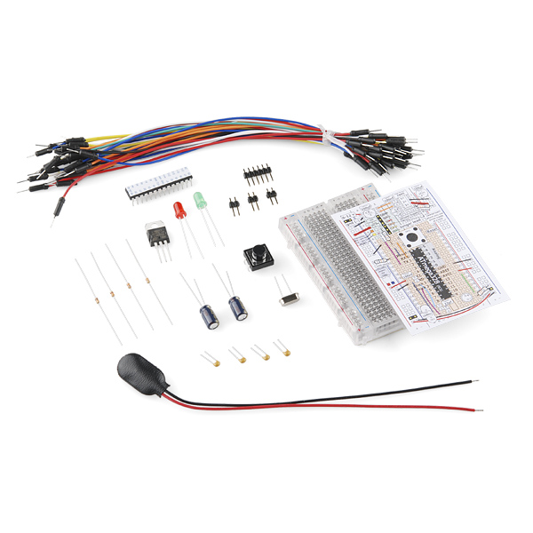
The SparkFun RedBoard Breadboard Kit allows you to assemble your very own Arduino-compatible development tool on a breadboard. If you've ever wanted to make a controller board from scratch or just understand how it all works, this kit is a good start.
We've put together all the parts you will need including an ATmega328 preloaded with the Optiboot bootloader. The breadboard overlay makes it easy to hook everything up correctly. Once you are finished, you will have a fully functioning Arduino-compatible controller on a breadboard.
An instruction booklet is included. Previous experience with a breadboard and electronics is recommended but not absolutely necessary.
Note: You will need an FTDI basic for loading code and communicating with the dev board. Check the related products down below.
Note: The schematic in the Assembly Guide isn't great so we've included a separate schematic file below.
Replaces:DEV-10786
- Assembly guide
- Clear breadboard
- Jumper wires
- Breadboard overlay
- ATmega328 with Optiboot bootloader
- All other components necessary to get up and running
SparkFun RedBoard - Breadboard Kit Product Help and Resources
Core Skill: Programming
If a board needs code or communicates somehow, you're going to need to know how to program or interface with it. The programming skill is all about communication and code.
Skill Level: Rookie - You will need a better fundamental understand of what code is, and how it works. You will be using beginner-level software and development tools like Arduino. You will be dealing directly with code, but numerous examples and libraries are available. Sensors or shields will communicate with serial or TTL.
See all skill levels
Core Skill: Electrical Prototyping
If it requires power, you need to know how much, what all the pins do, and how to hook it up. You may need to reference datasheets, schematics, and know the ins and outs of electronics.
Skill Level: Competent - You will be required to reference a datasheet or schematic to know how to use a component. Your knowledge of a datasheet will only require basic features like power requirements, pinouts, or communications type. Also, you may need a power supply that?s greater than 12V or more than 1A worth of current.
See all skill levels
Comments
Looking for answers to technical questions?
We welcome your comments and suggestions below. However, if you are looking for solutions to technical questions please see our Technical Assistance page.
Customer Reviews
No reviews yet.
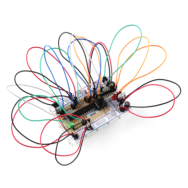
Neat kit. I would suggest selling this with pre-bent wires instead of the longer jumper cables. I do like the jumper cables, but only for quick and dirty tests; not on stuff that I might keep around long enough to program.
Agreed not only does it look messy, all those large loops of wire make the circuit more prone to electromagnetic interference than need be.
These kits are a lot more fun to use with 22ga solid wire jumpers.
How can I do a 3.3 output whit this for RFID Module?
Sorry for the delayed response. You should be able to replace the 5V regulator with a 3.3V regulator and have the board run at 3.3V instead. Technically 3.3V and 16MHz is out of spec for the ATMega328, but I've seen it used quite a bit without any problems.
I just put together this kit, and can definitely say that I am not in favor of the "ginorma jumpers"! Something like this should have the jumpers cut to size, to better match the tutorial and the layout. I thought there would be more space to do my own thing on the breadboard, and there is very little, however if the jumpers were the right size it would be much easier to see what is there vs what isnt.
I also found the following "annoyances":
There weren't enough red/black jumpers. those are the 2 main colors you want to know (where the power is).
The headers need to be tweaked to be usable. At least note it in the instructions. If I tried to put the short side in the breadboard it would pop out. But if I used the long side in the breadboard the FTDI board had trouble keeping it's connection. I had to move the plastic in the jump to the middle, and that worked better.
The layout was very frustrating to use on the breadboard. This might be my imagination, but it really appeared that even if I got one side of the layout right, the holes were off on the other side. I would recommend either creating a way to get the layout on the board better, or just create a larger layout not designed to be on the board, and more readable.
Anyway thanks for putting together this thing. Maybe I'll find a bunch of solid wire somewhere and re-do the wiring. It would help oh so much.
Oh and one last thing. The program that was on the ATMega chip was really weird, and made me wonder if I made it correctly. It was a blinking LED that kept going faster and faster until it went out. Occasionally it would start blinking again. I thought I had a short! Finally after correcting a minor wiring problem with the FTDI header I was able to download blink and found out it was just fine!.
.
Just what I needed. I want to learn how to hook up a plain 328 on a breadboard for a compact miny project. I am aware that buying these chips plain may require a programmer. This will teach me how to hook up all components required for minimal use of 328 chip. Thanks!
I was looking at the assembly guide schematic and noticed that Vcc and GND are tied together between the first and second nodes to the right of the programming header. This needs to be changed so that there is no connection between nodes 1 and 2. It would be easier to understand the schematic if there where appropriate dots placed at each node.
yeah, schematic is a bit misleading, we can fix that. the overlay is correct though, which is what most people will use to build this kit.