- Home
- Product Categories
- IMU
- DIYDrones ArduIMU+ V3

DIYDrones ArduIMU+ V3
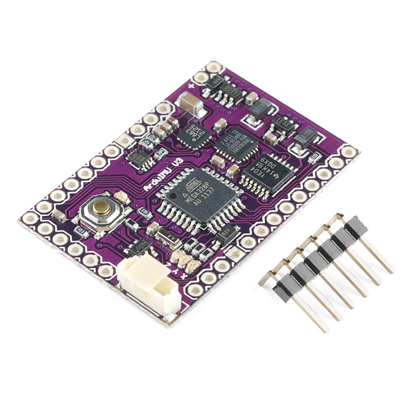
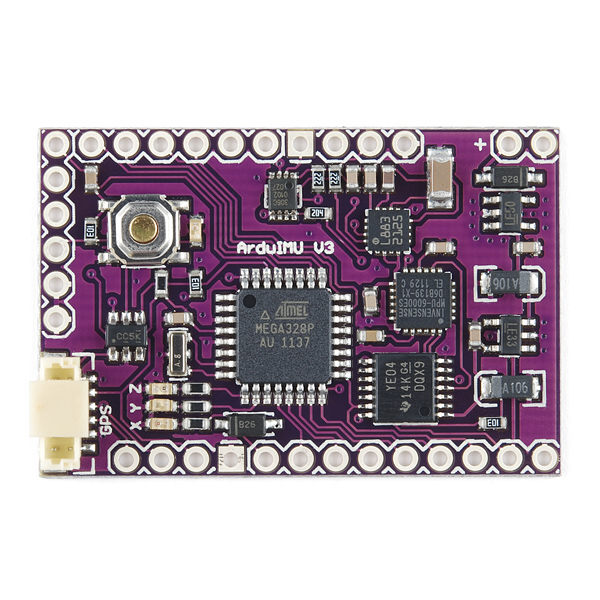
The ArduIMU+ V3 is the latest and greatest version of DIYDrones' smart IMU. This time they've made it smaller and faster by incorporating the new Invensense MPU-6000 MEMS 3-axis gyro and accelerometer as well the 3-axis I2C magnetometer HMC-5883L. With the GPS port and on-board Atmega328 microprocessor, the ArduIMU+ V3 is a tiny but powerful orientation solution.
This version of the board is pin compatible with V2, but unlike V2 it's also breadboard friendly! This device is suitable for any application from rockets to simple movement detection.
Having a hard time picking an IMU? Our Accelerometer, Gyro, and IMU Buying Guide might help!
Note: The board comes with a row of right-angle headers, as shown in the pictures. They come unsoldered.
- 3-Axis gyro with sensitivity up to 131 LSBs/dps and a full-scale range of ±250, ±500, ±1000, and ±2000dps
- 3-Axis accelerometer with a programmable full scale range of ±2g, ±4g, ±8g and ±16g
- Reduced settling effects and sensor drift by elimination of board-level cross-axis alignment errors between accelerometers and gyroscopes
- Full Chip Idle Mode Supply Current: 5µA
- On-chip timing generator with ±1% frequency variation over full temperature range
- User self test
- 10,000g shock tolerant
- Pin compatible with ArduIMU V2
- The 6 analog pins are now available!
- Arduino compatible and open source.
- 3 status LED's (RGB).
- I2C port with 3.3V translation.
- GPS port with FTDI autoswitch.
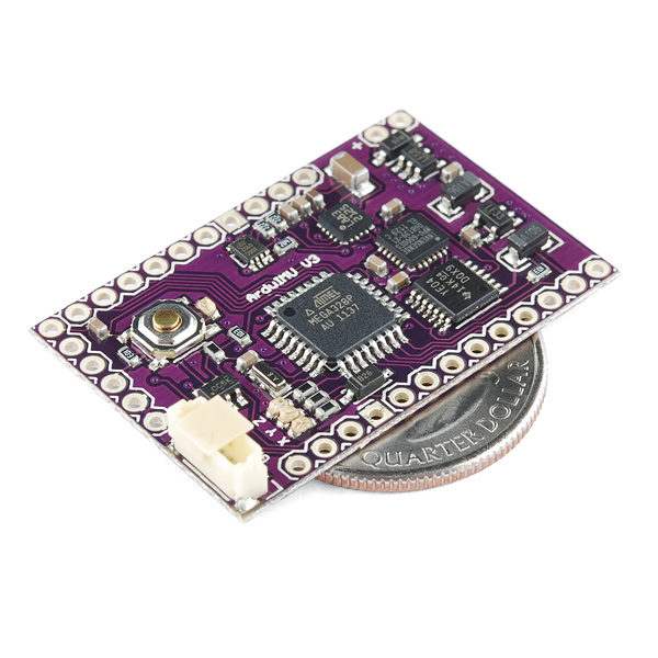
- 1.5" x 1.0"
- Schematic
- Eagle Files
- Google Code Page
- Datasheet (MPU-6000)
- Datasheet (HMC5883L)
- Datasheet (Atmega328)
DIYDrones ArduIMU+ V3 Product Help and Resources
Core Skill: Soldering
This skill defines how difficult the soldering is on a particular product. It might be a couple simple solder joints, or require special reflow tools.
Skill Level: Noob - Some basic soldering is required, but it is limited to a just a few pins, basic through-hole soldering, and couple (if any) polarized components. A basic soldering iron is all you should need.
See all skill levels
Core Skill: Robotics
This skill concerns mechanical and robotics knowledge. You may need to know how mechanical parts interact, how motors work, or how to use motor drivers and controllers.
Skill Level: Expert - In addition to having a solid foundation in robotics, you will need to know how sensors integrate with complex robotic systems. You will need to understand how to implement IMUs, UAV controllers, etc.
See all skill levels
Core Skill: Programming
If a board needs code or communicates somehow, you're going to need to know how to program or interface with it. The programming skill is all about communication and code.
Skill Level: Competent - The toolchain for programming is a bit more complex and will examples may not be explicitly provided for you. You will be required to have a fundamental knowledge of programming and be required to provide your own code. You may need to modify existing libraries or code to work with your specific hardware. Sensor and hardware interfaces will be SPI or I2C.
See all skill levels
Core Skill: Electrical Prototyping
If it requires power, you need to know how much, what all the pins do, and how to hook it up. You may need to reference datasheets, schematics, and know the ins and outs of electronics.
Skill Level: Competent - You will be required to reference a datasheet or schematic to know how to use a component. Your knowledge of a datasheet will only require basic features like power requirements, pinouts, or communications type. Also, you may need a power supply that?s greater than 12V or more than 1A worth of current.
See all skill levels
Comments
Looking for answers to technical questions?
We welcome your comments and suggestions below. However, if you are looking for solutions to technical questions please see our Technical Assistance page.
Customer Reviews
No reviews yet.
The FreeIMU library has been modified to work on the ArduIMU v3. The guy who did the porting, confirmed much better performance with the FreeIMU library than the original Ardu-IMU library. Please see http://www.varesano.net/projects/hardware/FreeIMU#lib-ports
I have been working with one of these for a while now and I have a few comments. The firmware it ships with and the firmware in the google code website for the V3 was not correct, it has an incorrect scaling factor for the accelerometer. The HMC-5883L magnetometer has two modes of reading outputs; continuous mode and single measurement mode. In continuous mode a max of 75 Hz output data rate is achievable, but with the single measurement mode an output data rate of 160 Hz is achievable. The arduino firware uses continuous mode. I have chosen to use atmel studio to program this board because debugging/changing arduino code in the old arduino IDE (this board only uses the old IDE apparently) is a nightmare.
This board has the capability of giving 3 gyro readings, 3 accelerometer readings, a temp reading from the MPU-6000 for correct gyro scaling, three magnetometer readings and gps capability. It is well known that the best way to combine all this data is through quaternions with an Extended Kalman Filter (EKF) to avoid singularities at 90 degree pitch and to get an accurate estimate of the orientation/position without the integral drift effect. Now, with all this said, the board ships with an 8-bit 16Mhz atmega328p MCU!! I have tried at great length to implement a quaternion based EKF at 100Hz output rate (which is required to stabilise an inherently very unstable helicopter) but have so far failed on this chip, it is just too slow. I have now resorted to using the atmega328p for gathering the raw data from the sensors and sending it all to a much faster board for processing.
Therefore if you looking for something that is able to give you accurate, singularity free orientation/position estimates at fast update rates, then I don't recommend this board. If next generations of this board are board shipped with more powerful MCUs that are capable of these types of calculations then they would be a great development board and an amazing way to learn industry standard sensor fusion algorithms.
Another thing is that all on board sensors need calibration before use. I highly recommend using this guide: http://www.st.com/web/en/resource/technical/document/application_note/CD00269797.pdf and this guide: http://www.adafruit.com/datasheets/STMEMS.pdf (both from ST micro) to help with that. This is where you find out what offsets and scaling factors are.
Hi, thank you for posting this, we are alsp planning to use the same approach. Would you be so kind to share the code you mentioned for reading out the sensors? Thanks!
Does anybody know if I can connect a 5v FTDI cable to this device? I'm anxious to begin programming it, but I don't have a 3.3v cable. Will I damage the sensors if I hook it up to 5v?
any word on power usage to detect estimated distance moved?
what is the power usage when taking readings? I want to use this to measure approximate distance traveled, kind-of like a pedometer but for anything. Resolution drifting by up to 5 feet per second would work.
what is the power usage when taking readings? I want to use this to measure approximate distance traveled, kind-of like a pedometer but for anything. Resolution drifting by up to 5 feet per second would work.
Sorry, I don't understand why this posted twice.
how do I delete this post?
DON'T BUY THIS!
This board is utter trash. The firmware provided is useless. Even with every fix I have scoured off of the internet over a period of 18 months, there is still a > 1º/sec drift on the yaw axis, and random spikes on every axis. Sparkfun, I respect you as a company, but I can't keep respecting you if you keep selling expensive, useless parts like this.
I'd say at least I got a paperweight out of it, but the board is too small and light to hold down even a single sheet.
I think I know the answer to this but just for clarification - Is there a possibility of running this with both a microSD breakout board and an XBee module? If so, which ports would the microSD connect to? http://www.skpang.co.uk/catalog/breakout-board-for-microsd-transflash-p-639.html
I would like to connect a 10DOF IMU to an Arduino board that is connecting to servos but don't know what boards are the most compatible. Any suggestions?
I would like a newer version of labview to view data arduimu. Anyone have?
I wonder how do the outputs of accelerometers appear gravity value of the land, when the stop plate. For me is providing high values. thank
For anyone who is interested in seeing this IMU work, here is some Aduino code that hopefully works for you. There are 2 projects, ArduimuV3_v1 and ArduimuV3_v2 that will output roll, pitch & yaw data. There are also gyro & magnetometer cal routines. If you have a GPS unit, it will also output that as well. The difference between v1 & v2 and that v2 also outputs pressure-altimeter data from the BMP085 sensor (DIY Drones). This project uses libraries available from DIY Drones (AP_GPS, FastSerial, etc) so will have to get those. The url for these are in the code. There is a Layout.txt file which documents as best I could the board layout - i.e what pins are used on the ATMEGA328 for the various sensors & ports.
https://code.google.com/p/arduimu-v3-ahrs-improvements/source/browse/
There is also a Cube.Zip Processing app which you can feed the output of this IMU to see the results.
http://www.youtube.com/watch?v=HMCxAON4N_o&list=UUwWpRoa_XvfbIqSCvv9mOQg&index=1
If I were to hook this up to a Raspberry Pi that was 3.3v, would I need a Logic Level Converter like this https://www.sparkfun.com/products/8745 ? I see that it has a I2C port with 3.3V translation, but I'm not really sure what that means or if it has anything to do with what I'm wanting to know. I am trying to hook it up to a Raspberry pi via a serial connection on the GPIO pins (RX and TX). I would like power it with the raspberry pi on the GPIO pins too if it isn't too hard.
When I tried powering the ArduIMU with the Rpi, it just couldn't give the IMU enough power and I ended up having to supply a separate 5V into the v in pins on the ArduIMU.
I am going to use this to create a tracking system for my telescope. Does anyone have any advice on putting this in some kind of protective case? It doesn't have anywhere to screw it down so could I just use some double sided tape or something and stick it? It doesn't have to be too protective, I just want to put it inside of something.
Hot glue, velcro and double sided tape all work well. You can see a bunch of different enclosure options here.
surrounding metal and magnetic objects will affect the performance of magnetometer? i m using it on my robot and if yes how can i overcome this problem?
Yes, hard and soft iron (like in speakers or motors) or any magnetized material can affect the reading of the magnetometer and basically add or distort the magnetic field reading from the earth. Most magnetometers allow you to offset or calibrate the sensor for hard/soft iron (see the datasheet). However, the field needs to be constant in order to easily correct for it, if it changes a lot, then the offsets will be much more difficult to obtain.
I just flew this on a rocket for the first time this past weekend using a uBlox for the GPS.
The results look surprisingly good - certainly correlating well with the visual behaviour of the airframe as well as the other avionic data - acceleration and baro altitude used for recovery.
Does anyone the rate you can get readings from arduimu?
I'm not seeing a tutorial page or anything- what exactly does this provide, out of the box? (In simple terms)
I want to know, how can i calculate the MAG_OFFSET? This part of the ArduIMU (DiyDrones) code: // Magnetometer OFFSETS (magnetometer calibration) (only for ArduIMU v3)
define MAG_OFFSET_X 0
define MAG_OFFSET_Y 0
define MAG_OFFSET_Z 0
I realy made a big search and just find nothing.
The code doesn't work with this version of the board. That's rather a shame.
http://www.diydrones.com/forum/topics/arduimu-v3-all-axes-output-wrong-values
Request for more info: Would this work with GPS-10294 Arduino Mega compatible UAV Controller? If does, where can I find some installation manual? Thanks in advance. Daniel
They're both UAV controllers, so you'd typically use one or the other.
EDIT: I misspoke, this one is not a controller (was thinking of the ArduPilot). Check the DIY Drones website, they should have information on interfacing them together.
What firmware version do these ship with? The output format seems different than any of the options on the Google Code Page.
Does anyone know whether the magnetometer will still work properly if the IMU is tilted at 90 degrees (or even more) from vertical? I would like to put an IMU in a belt buckle...
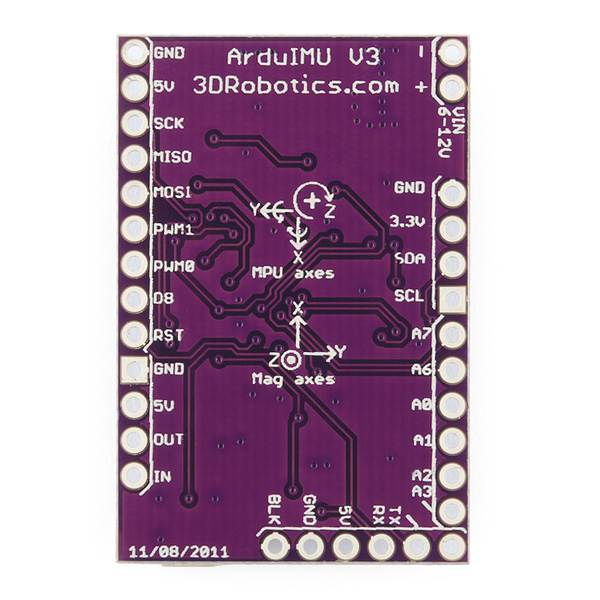
Unless I'm going crazy (and it has been known to happen), the silkscreen on the back indicating the magnetometer axes suggests a left hand coordinate system. Is that correct?
I can't see how it would be problematic, it's just an unusual choice. I don't remember a single fields/physics class I've ever had in which they didn't drill the "right hand rule" into our heads.
This product is not listed as the replacement for the V2. Should it be listed as such or is there a subtle change in function?
I just received one of these, but I�m not very familiar with Arduino. I also have a TTL-232R-3v3 cable and have the unit running and can see that several values are being sent at 115,200 baud. I loaded the 1.9v into the Arduino IDE 1.0 but the code does not verify. What board definition do I use to download?
Compile with Arduino 23 and it will compile correctly.
Can anybody give me some advice about what GPS units work/are best to use with this board?
This one is probably the best GPS: http://www.sparkfun.com/products/9566 Here is a very similar one: http://store.diydrones.com/GS407_U_Blox5_GPS_4Hz_p/spk-gps-gs407.htm Here is information that you may find helpful: http://code.google.com/p/ardu-imu/wiki/WhatNeed
Also, could someone please clear something up for me? I note the use of an I2C level shifter. I was under the impression that as long as the SDA/SCL line pull-ups were tied to 3V3 (rather than 5V), communication should still work? Is this a speed thing? Or just good practice?
Very-much-like! Am going to seriously consider getting one of these in my next order.
How come ya'll didn't take the pick-n-place cap off off the GPS connector before pictures?? Some people might be wondering what that is... it allows automated equipment to pick up the connector from a reel, or tray and place it on the PCB.
Just slipped my mind actually!
Like!
It appears that the magnetometer is connected to the Atmega, as opposed to the aux input of the MPU? Does that mean it's unable to use the magnetometer with the DMP that's onboard the MPU?
Looks like it. The docs on the 9DOM DMP are however not available so you can't implement any 9DOM DMP code yet. This will however limit you in the future if any docs surface or if you just wanted to read the raw magnetometer readings from the MPU6000 (something already possible).