- Home
- Product Categories
- Audio Boards
- SparkFun FM Tuner Basic Breakout - Si4703

SparkFun FM Tuner Basic Breakout - Si4703
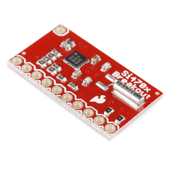
This breakout for the Silicon Laboratories Si4703 FM tuner chip is a little more stripped down than our FM Tuner Evaluation Board. If your project already has an amp and just needs a full-featured FM tuner, this is the board for you. Beyond being a simple FM radio, the Si4703 is also capable of detecting and processing both Radio Data Service (RDS) and Radio Broadcast Data Service (RBDS) information. The Si4703 even does a very good job of filtering and carrier detection. It also enables data such as the station ID and song name to be displayed to the user.
Using this board we are able to pick up multiple stations just as well as with a standard FM radio. The board breaks out all major pins and makes it easy to incorporate this great chip into your next radio project.
- Schematic
- Eagle Files
- Datasheet (Si4703)
- Programming Guide (AN230)
- Programming Guide (AN243)
- GitHub (Design Files & Example Code)
- GitHub (Library)
- Hookup Guide
SparkFun FM Tuner Basic Breakout - Si4703 Product Help and Resources
Si4703 FM Radio Receiver Hookup Guide
August 13, 2015
Add some tunes to your project with the Si4703 FM Radio Receiver Breakout.
Logic Level Conversion
If you are using a different microcontroller that is 5V, you will need to connect to the respective I2C pins, and match the logic levels. Make sure to add the 4-channel bi-directional logic level converter between SDIO, SCLK, RST, and GPIO2.
Core Skill: Soldering
This skill defines how difficult the soldering is on a particular product. It might be a couple simple solder joints, or require special reflow tools.
Skill Level: Noob - Some basic soldering is required, but it is limited to a just a few pins, basic through-hole soldering, and couple (if any) polarized components. A basic soldering iron is all you should need.
See all skill levels
Core Skill: Programming
If a board needs code or communicates somehow, you're going to need to know how to program or interface with it. The programming skill is all about communication and code.
Skill Level: Rookie - You will need a better fundamental understand of what code is, and how it works. You will be using beginner-level software and development tools like Arduino. You will be dealing directly with code, but numerous examples and libraries are available. Sensors or shields will communicate with serial or TTL.
See all skill levels
Core Skill: Electrical Prototyping
If it requires power, you need to know how much, what all the pins do, and how to hook it up. You may need to reference datasheets, schematics, and know the ins and outs of electronics.
Skill Level: Noob - You don't need to reference a datasheet, but you will need to know basic power requirements.
See all skill levels
Comments
Looking for answers to technical questions?
We welcome your comments and suggestions below. However, if you are looking for solutions to technical questions please see our Technical Assistance page.
Customer Reviews
4.3 out of 5
Based on 7 ratings:
1 of 1 found this helpful:
Great for audio - metadata, not so much.
Works great for tuning and listening to radio stations - local stations picked up in mono with just a single piece of breakaway header soldered as an antenna (less than 1cm of metal). With a single 15cm segment of jumper wire, I can pick up perfectly clear stereo audio. Pretty much perfect!
However, the RDS implementation is hit or miss - to the point of sometimes being unusable. With static text it seems to do just fine, but there's something about the 'scrolling' type of text that just breaks it. Readouts come back filled with incorrect characters, and often seem to have remnants of previous readings still in place, leading to a jumbled mess.
I would also like to point out that the library is made up of poorly and inconsistently formatted code - I went digging to see if I could figure out what the board was doing and I had to spend 5 minutes cleaning the code up before I even wanted to look at it.
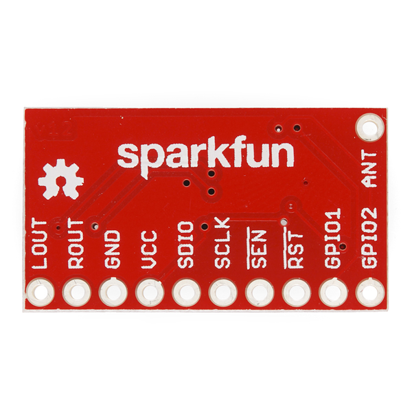
Another point off for the lack of feature documentation - pointing to a different board for the hookup guide, which just tells you to connect X on the board to Y on your Arduino. Why are we told to connect GPIO2? The code doesn't use that pin and neither does the library. I don't expect you to rewrite the documentation for the chip but at least a brief description of the pins you broke out would be nice. Took me searching through the chip's documentation to figure out what "SEN" was - it's serial enable. Useful? Who knows, but you broke it out and then left the end user to dig through pages of documentation.
1 of 1 found this helpful:
Excellent FM Radio project board!
Teamed up with a 3.3 volt Arduino Pro Mini, a Nokia 5110 LCD display, a Rotary encoder, and an old TDA1517P amp module, the Si4703 Breakout Board made an awesome project I now use everyday.
Got it all running in one rainy weekend. Still some capabilities yet to be explored (RDS and RBDS). Makes for the type of radio project you can keep adding features to (date, time, alarm, etc...). Surprisingly great reception and sound quality. Very happy.
3 of 4 found this helpful:
what to do?
Your product when used with your supplied software is in violation of the Si4703 specifications:
http://www.silabs.com/documents/public/data-sheets/Si4702-03-C19.pdf
The Si4702/03-C19 seek/tune performance may be affected by data activity on the SDIO bus when using the integrated internal oscillator. SDIO activity results from polling the tuner for status or communicating with other devices that share the SDIO bus. If there is SDIO bus activity while the Si4702/03-C19 is performing the seek/tune function, the crystal oscillator may experience jitter, which may result in mistunes and/or false stops. SDIO activity during all other operational states does not affect performance. For best seek/tune results, Silicon Laboratories recommends that all SDIO data traffic be suspended during Si4702/03-C19 seek and tune operations. This is achieved by keeping the bus quiet for all other devices on the bus, and delaying tuner polling until the tune or seek operation is complete. The STC (seek/tune complete) interrupt should be used instead of polling to determine when a seek/tune operation is complete.
excerpt from Sparkfun provided code:
//Wait for the si4703 to clear the STC as well
while(1) {
readRegisters();

if( (si4703_registers[STATUSRSSI] & (1<<STC)) == 0) break; //Tuning complete!
}
note that example code from siliabs does not violate the specification.
Sparkfun code can be made compliant with a hardware modification to use an external oscillator but the breakout board makes no allowance for this.
Fun FM radio module for Arduino projects
I bought this to use with an Arduino Nano and I got it running without much issue. I found various free example sketches and think the audio quality is very good. I'm just using a 2 foot piece of wire for the antenna and it receive great. My 2.4" TFT display does create RF noise that I need to control, but without it this module works great!
Great breakout board!
This is a great breakout. Perhaps my project was a bit complicated for a beginner, but diving in is the best way to learn. I like having this option to breakout to a separate amp as opposed to the evaluation board. Please don’t stop manufacturing this board. It’d be nice to have an identical breakout for the Si4135 too.
0 of 1 found this helpful:
Jury is still out.
It'll be quite a while yet until I put all of the pieces together and start coding everything. I hope to be able to plug it in around March of next year.
Excellent Receiver.
I used it to build a stereo FM Receiver and it works from first try. It will be much better if there was SMA/RP-SMA/U.FL connector to connect FM antenna instead of the single hole which does not have a ground and not breadboard friendly.
See this video: https://youtu.be/a82DHU4T_aY
Circuit is using:
1 x SparkFun Breadboard Power Supply Stick - 5V/3.3V (https://www.sparkfun.com/products/13032)
2 x SparkFun Mono Audio Amp Breakout - TPA2005D1 (https://www.sparkfun.com/products/11044)
1 x SparkFun FM Tuner Basic Breakout - Si4703 (https://www.sparkfun.com/products/11083)
1 x Arduino Pro Mini 328 - 3.3V/8MHz (https://www.sparkfun.com/products/11114)
Connections and firmware are here: https://github.com/mkhuthir/repo_SDR/tree/master/Si4703
There are now a lot more 32-bit microcontrollers in use than when this product was first introduced. Because many of them support i2s digital audio, I'd like to see a version of this product based on the Si4705 which adds i2s output. If you revised this product to the Si4705, I think you'd have the only i2s capable FM tuner breakout on the market.
I've seen others ask for a si4737 rev and it also has i2s output.
So, have you guys considered a replacement to this board? Such as the si4737 with FM/AM/WB and RDS/RBDS. I really wish you guys still had the si4707 breakout haha. I really want to build a radio with fm and the weather band, and I can't find another IC that does so. Thanks!
I'm using the board to prototype for a product. I'm a little confused by the schematic, the inductor L1 is in series with the antenna and a capacitor, C5, to ground. Looking at spec sheets AN231 and AN383 this appears to be incorrect. The inductor should be connected from the antenna to ground, therefore forming a resonant LC circuit with the antenna capacitance. On the eval board, with amp and headphone socket the inductor is placed correctly. I just wanted to check that I am not missing something and that this is an error?
Can I work with a 5v microcontroller , or I need to use a logic converter to work with this module
Any chance you guys could get the FM receiver chip from Silicon Labs that includes the weather band and SAME decoding? I have not had any luck finding a supplier of chip with the weather band and SAME decoding in small qty. You have a few FM tuner/receiver options in your catalog, but none with the option to handle weather.
I will suggest this to our main research person as a product suggestion. Thanks!
Frontier Silicon have just released a module, referred to as the 'Tuscany', which supports Bluetooth, DAB, FM and USB docking which I am dying to get my hands on. Any chance it would surface here in the form of a breakout?
Dangerous Prototypes has been working on a board for some time. Last I checked, they were revising the board layout due to discontinued support components.
I have a project that could use that also!
YES! I've been wanting to build my own clock radio w/ NOAA radio for some time now but couldn't find any way to get the chip.
I'm also working on a project that needs an integrated weather band receiver. A breakout board with this WX band chip would really help things along!
Hi, I'm having trouble to get the board working. I have hooked everything up and can communicate with the provided example code. For the antenna I have soldered a 1.1 metre long wire on it and I'm getting 20-ish RSSI, but on every frequency I just hear static. Has anyone had a similar problem before? -edit- Additional information: I have also tried playing around with the configurations been toggling DSMUTE, MONO, RDSM from reg 02h RDS,DE from reg 04h
Voltage = 3.3V I have used a scope on Lout and Rout and didn't see anything but static
How did you connect an audio output to the chip? I've tried connecting headphones strait to Lout Rout, any help appreciated.
Additional information for this problem. Following are the # in the registers after initialization: (all look correct) Si4703
Device_ID 0x1242 Chip_ID 0x1253 Pwr_Config 0xE001 Channel 0x003C Sys.1 0x0000 Sys2 0x0008 Sys3 0x0000 Test1 0xBC04 Test2 0x0000 Boot_Config 0x0004 Status_SSI 0x000C Read_Channel 0x003C
STC 0 XOSCEN 1 DeMute 1 Si_Enable 1 Tune 0 Freq 995 Current-Freq 995 Volume 8 Current _Vol 8 Current_SSI 12
Current_SSI seems low but I should still hear something other than noise.
Any luck solving this problem. I have the same thing. I'm getting about 8-12 SSI-ish. All registers have correct hex # in them, but all I get is a white noise on the speaker. I also played around with the configuration but with no results.
Any one make this thing work? If so, what did you use for an antenna?
Thanks, rm
I have this wired up and it appears to be talking to my Arduino Due (in a remarkably short amount of time). When I try and program this or change channel though it just polls forever, like tuning or seeking is never completing (and I get no sound from it).
while(1) { readRegisters(); Serial.println("Polling"); if( (si4703_registers[STATUSRSSI] & (1<<STC)) != 0) break; //Tuning complete! }
anyone out there got example working code they could share?
I have the same problem.
What antenna would you recommend for using with this board?
You can solder a couple of feet of wire to the antenna pin hole or there are other options. More info found in Si app note AN231.
Re Example code - the latest version of the programming guide is at AN230 and AN243
Hey Sparkfun peeps, can you update the links to be to these (newer, better) docs? You'e linking to 0.61 which is < 0.9 that jdf2525 links to above.
Getting it updated. Thanks for nudging us about it!
Has anyone been able to use this to decode time from the station RDS signal? According to an243 page 13 it is possible. Just want to know if anyone has fount it reliable.
Is there a library for the mbed lpc 1768 as well?
Is there a library for mbed lpc 1768 as well?
I am trying to get Mr. Seidle's fine-looking example code to run. I am getting the following error during compilation: "class TwoWire has no member named 'receive'". I know this problem has to with the version of Wire.h, so where can I find the appropriate version. And where do I put it when I get it? Or maybe there is another work-around? I can't believe there is no "document control" procedures for all these include files. How is anyone to know what's going on??? Thank you for your help. Dave Anderson
Same problem here. Any help?
Wire.h is updated. change wire.send to wire.write and wire.receive to wire.read
I am looking to build my own car stereo - Does anyone no of an audio processor that would take the output here and allow me to fade between front and back speakers?
I am having problems getting the supplied library to work with the Mega2560. Any hits or pointers would be appreciated.
To Member 552599: Did you find an solution to the problem. I have the same sympton. My ssi reading are between 8 to 12. All registers indicate correct hex # but all I get is a steady hiss from Lout & Rout.
How hard would this be to use with a raspberry pi? or is there a better alternative?
I paired one of these with a Arduino Yun to get http (Web Service) access. It worked great. It was a bit of work sorting out how to route it all through a level matching circuit but it works great. If you have a web page to access the tuner you can change the radio settings from the browser on your phone (or another computer, of course). I only needed one of the level conversion boards to get it to work.
Has anyone had any luck using a software I2C library with this radio? I have my A4&5 pins tied up with other components on my Uno. If anyone has a library for using other pins could you share? Or detailed instructions on how to use some of the existing soft I2C libraries to make it work? Big Thanks!
I've tried both this part and the eval board and keep hanging at "Initializing I2C and Si4703." Anyone have any luck with either of these parts and the example code here?
I'm working at a project: http://www.youtube.com/watch?v=cZ1n-3FHe3g The design is by: http://www.vwlowen.co.uk/arduino/radio/radio.htm It's easy to build, only a few parts. I'm going to rebuild it on a Flowerpad pcb: http://www.elecfreaks.com/store/flowersoic-protoboardmega-shield-p-379.html
Hello,
A few months back I ordered this FM tuner. While programming and testing my circuit with arduino controller I used the power supply from my arduino uno. I didn't use the arduino itself, I placed the programmed microcontroller from arduino in my own circuit. Finally everything worked and I connected everything to another power supply, a 7805 voltage regulator. I checked the voltage and it was 5V, a bit higher than te voltage from my arduino. But the FM tuner should work on 5V as well (5,5V maximum). The only thing that has changed was the power supply, from arduino to a 7805 regulator. When I turned everything on, the fm tuner breaks. The ground and the VCC are shorted.
Pas week I oredered a new fm tuner to finaly finish what I started. I double checked the whole circuit and I couldn't find any faults. The same thing happend again, as soon as I turned the powersupply on the fm tuner breaks.
Any suggestions??
Sorry to hear about that! Take a look at the Si4703 datasheet again. The absolute max for VIO is 3.9V and VIO is tied to VCC (see schematic) which is 5V. It is best to power this board anywhere between 2.8-3.3V.
If VIO is supplied with 3.3V, does the I2C bus then need to also be at 3.3V or can a 5V bus work?
My thought is "no" - if that's the case, how does one go about connecting the 5V I2C bus to the 3.3V chip?
You can use a 3.3V part on a 5V I2C bus if you're careful. I2C actively pulls the signal to ground for low signals, but lets it float for high signals. Therefore, if the pullup resistors (on the radio board) are connected to 3.3V (which they are), and you don't accidentally make the SCL and SDA pins on your microcontroller high (5V) outputs (which won't happen if you only use those pins for I2C), then everything will work fine.
OK, but in the schematic is the voltage maximum 5.5V. http://dlnmh9ip6v2uc.cloudfront.net/datasheets/Wireless/General/Si470x-breakout-v13.pdf
The voltage from my regulator is 5.06V and the voltage from the arduino is 4.92V. Thats almost the same. I cant see why the fm tuner would break at that voltage because it worked fine with the power supply from the arduino..
The schematic is incorrect, we'll get that fixed. VCC cannot be 5V since it is connected to VIO. VIO sets the absolute max.
I'm not sure why it initially worked with 5V, but it is not suppose to.
Please contact techsupport@sparkfun.com and they can get you another board. Tell them to refer to this comment.
This library does not work on the Mega 2560. I have a UNO and a MEGA, it works on the UNO but not the MEGA. Can you pls help me figure it out?
Neat board; got it hooked up quickly. The Arduino library works well, but it has hardcoded settings for Europe. Needed to edit for USA.
Is there a sketch that is known to work for SI4703 and is there anything else than the pinning stated here: 3.3V : VCC , GND : GND , A5 : SCLK , A4 : SDIO , D2 : RST to respect? Thank You for your help
There is an example arduino sketch in the document section above and there are comments in the sketch that indicates the pin connections.
Would it be possible to take the audio from this device and save it to the SD card on my arduino? Or are other hardware components needed to handle the audio? I want to save the audio to an SD card in a format that I can remove the card from my arduino and then play it on my computer.
I have a few 4737 tssop chips as samples, and i can say that they ROCK. If SF can get them you should. QFN will definatly need a breakout, but the tssop is doable by hand.
As far as I know, the AM/FM/WB combo chips don't do SAME decoding. The Si receivers that do are covered by a NDA. However I would like to see the Si4703 on this board replaced with the Si4737. I've written the Arduino SAME library. Using XR-2211's, it can decode the SAME messages out of any supplied audio stream. The details of the project can be found here:
http://www.raydees.com/Weather_Radio.html
Maybe SF would build these?
I noticed you copied the same mistake from the eval board schematic regarding the RST pin. The Si-4703 datasheet says "Driving the RST pin low will disable the Si4702/03-C19"
Drive RST high, the chip will come out of reset mode and will enter I2C mode since SEN is pulled high.