- Home
- Product Categories
- Arduino Shields
- SparkFun AVR ISP Shield - PTH Kit

SparkFun AVR ISP Shield - PTH Kit
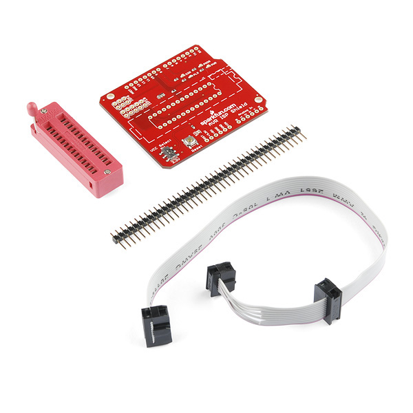
Did you know that your Arduino can spawn other Arduinos? Don't worry, it can't do it autonomously so you won't wind up with a replicator situation (-gate, not -Trek). The point is, the ArduinoISP sketch allows your Arduino to act as a programmer. You can use this awesome power to burn bootloaders onto ATMega chips, turning them into Arduino-compatible microcontrollers! In the past, this required a breadboard and a whole mess of jumper wires but we've just made it a ton easier on you with the SparkFun AVR ISP Shield!
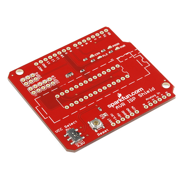
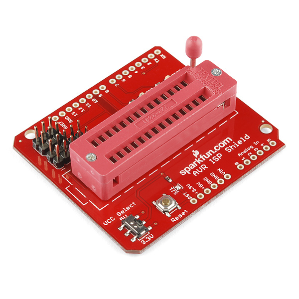
This shield, once assembled, gives your Arduino a 28-pin ZIF (Zero Insertion Force) socket so it can grab onto unsuspecting ICs. The socket is wired to work directly with the ArduinoISP code, but burning bootloaders isn't the only thing you can do with it. We've also connected the serial I/Os so that if you're a programming ninja you can do cool tricks like programming ICs using the bootloader on-the-go.
- AVR ISP Shield
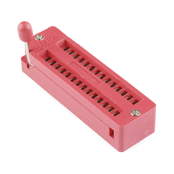
- 28-Pin ZIF Socket
- AVR Programming Cable
- 40-Pin Straight Headers
SparkFun AVR ISP Shield - PTH Kit Product Help and Resources
Core Skill: Soldering
This skill defines how difficult the soldering is on a particular product. It might be a couple simple solder joints, or require special reflow tools.
Skill Level: Rookie - The number of pins increases, and you will have to determine polarity of components and some of the components might be a bit trickier or close together. You might need solder wick or flux.
See all skill levels
Core Skill: Electrical Prototyping
If it requires power, you need to know how much, what all the pins do, and how to hook it up. You may need to reference datasheets, schematics, and know the ins and outs of electronics.
Skill Level: Rookie - You may be required to know a bit more about the component, such as orientation, or how to hook it up, in addition to power requirements. You will need to understand polarized components.
See all skill levels
Comments
Looking for answers to technical questions?
We welcome your comments and suggestions below. However, if you are looking for solutions to technical questions please see our Technical Assistance page.
Customer Reviews
4 out of 5
Based on 1 ratings:
1 of 1 found this helpful:
Good, but...
I kind of wonder about the quality of the "TFXTOOL" ZIF (3M makes a TXTTOOL - note the second character - ZIF socket; This is clearly made by someone not quite affiliated with 3M), but it seems good and it works. I'm able to program things fine.
I would have liked the LEDs to do something as I'm programming it without an Arduino (using an Adafruit USBTiny) - only the power LED lights. It would have been nice to see if there was activity on the MISO/MOSI lines, but I can live with that.
Oh, this is the second Sparkfun product I purchased that had a problem with one of the surface mount LEDs. I'm not sure what Sparkfun is doing wrong with these, but this one had a missing LED. The last product with surface mount LEDs had a tombstoned LED. Not a big deal, but should be caught by QA ("All parts on board?").
Edit: Sorry, I was drunk when I wrote that. I had to use a calculator for that math! Please disregard what I said. I love sparkfun. Can an admin please delete this comment?
If you don't support the shops that make your life easier, and they disappear, leaving behind soul-less corporate giants that could care less if you get what you need let alone order, then who's fault is it really?
Remember, PROFIT is a byproduct of good business. Its not a dirty word, nor is it wrong.
Yep, and we employ 150 people. So for each sale of this board, we all get 8 cents... Not to mention the electricity bill and rent...
Please add a big warning label on the description to really look at the schematics before using this shield. I have used this programmer for two days and bricked four ATMega328p, perhaps destroying them partly as they don't seem to work correctly.
Bootloader programming seems to work reasonable well with the shield, but then you load the sketch with the command "Upload using programmer" and things turns really weird. From the comments I understod that VCC is connected to the A5 line of the AtMega328. This line is used by the standard Wire library. I.e things get ugly when then newly programmed ATMega328 reboots and starts using the line. Other strange things happens if you use the Serial-library as the serial lines are connected to the system serial lines... and just interfere with everything communicating with the bottom shield.
Then people are mentioning a 10uF capacitor.. please document why and how in the non-existing instructions on how to build this shield.
I might have had my expectations wrong, but built my own programmer on a prototyppe board and then decided that I need a zero insertion socket and Voilá, this shield solves all that. Instead I got two days of problems, buying and modifying an AVR Dragon-board to unbrick the damaged chips, not to mention downloading and configure the AVR Studio (bad software, bad drivers) etc... If you are to build a multi-device programmer, please have a look at the AVR dragons approach were you need jumper wires to connect the power to the different pins on the different chips.
The description text claims the shield can do a lot more than just burning the bootloaders, but it is really not done for programming standard sketches without modifications. Please tell people this directly in the shield description! Ps. Really love the other work you do, but this device was too badly documented. Ds.
Could SparkFun add a holes to solder in a 10uF cap to disable reset? Testing on both my Duemalianove and Uno it appears it is needed, even after bridging the gap to the reset resistor. Seems to be plenty of room!
Excellent suggestion. I think it's been suggested already in the comments as well.
I'll look into adding that in the next rev.
Thanks!
Getting ERRORS with certain ATmega chips versions
The Arduino Uno board (and some others) use the ATmega328P microcontroller, which is the picoPower version of the ATmega328. When you try to burn the Arduino bootloader to an ATmega328 (version without picoPower), the Arduino IDE will return an error. The problem is that the ATmega328 and the ATmega328P has two different device signatures. For a solution to the problem have a look at http://robotics.org.za/index.php?route=product/product&path=46&product_id=235 Hope that helps
Thanks for posting your solution. Much appreciated!
I have used this to program the ATMega328P AND the ATTiny85 If you use the Arduino 1.5.6-R2 software then instructions here are not quite up-to-date. Download this software: https://code.google.com/p/arduino-tiny/ create a hardware directory in your sketch folder (this is created for you under window in your Documents area as "Arduino". ... if you follow earlier instructions, you will get compiler errors for attiny. Once you have copied those tiny cores, you will see extra items under "Boards" in the IDE. Choose wisely.
You do not have to use AVRDude to program either of these chips. To set fuses for ATTiny and other non boot loader chips, choose the right board, (attiny options now added) and "Burn bootloader" - this does not load the boot loader for ATTiny but does set fuses. Then hold down the shift key while pressing the "Upload" button. This will ISP load your sketch to the chip. If you use "Blink" as an experiment, change the led pin to 0. Then connect an LED to hardware pin 5 and Ground (Hdware PIn 4).
You will get 2-3 lines of errors AtTiny Ignore them. they don't matter. (example below)
avrdude: please define PAGEL and BS2 signals in the configuration file for part ATtiny85
If you ever get this comment - avrdude: stk500_getsync(): not in sync: resp=0x00 and you're anything like me. You can rip your hair out searching on the net. I bought the above mentioned board and looked everywhere for an answer. Oddly enough I couldn't find one as everyone's advice gave no help. But looking at someone else's post they mentioned something about virtual ports. Never heard of that before so I when to device manager and looked at my Arduino and saw the Baud Rate was 9600. I changed this to 19200 as per ArduinoISP sketch on 1.05 and gave it a whirl. It worked.
Still can't get over how bad the documentation is for this module. If I had the knowledge I'd make one, but so far my problem was a tiny one. Lucky me.
Is there somewhere I can get a step by step tutorial with pictures for this product? I'm using an Arduino Uno and ATMEGA328P-PU chips. I check what was available before buying this and thought, it looks easy. While the assembly of the kit was simple, the use has been a pain. The documentation available is extremely poor on this product and by judging the age, Sparkfun should have done a better job than this. I followed the ArduinoISP Tutorial which by the way is a cop out of actually producing a product specific tutorial. I've wasted days looking at youtube and searching the net. Got to the point I'm trying every combination to get it to work. Past uploading the sketch successfully I keep getting. avrdude: stk500_getsync(): not in sync: resp=0x00 Board setting Duemilanove w/ Atmega328 Programmer set to AVR ISP or Arduino as ISP gives the same response.
Suggested improvements:
So I am able to burn the bootloader via Arduino IDE (1.0.5) using my duemilanove as the ISP. When I try to then upload a sketch to the chip while in the sheild (using "Upload using programmer"), it fails with:
avrdude: stk500_getsync(): not in sync: resp=0x00
I was able to upload the sketch by putting the boot loaded chip in the due with no issues, but that defeats the purpose of having this shield. Any suggestions for troubleshooting not being able to upload sketches? Realize the 0x00 is a generic "cannot communicate error message", but seems bizarre that it works fine for burning the boot loader.
Anyone suggestions on "Upload using programmer" to With a duemilanove as the ArduinoISP, I am able to burn the bootloader for atmega328p just fine (done it with two different blank chips).
I have had mixed results with this shield. When I was on my Dell, I had a few issues, but could almost always program a 'virgin' chip. After that it was difficult to get a successful re-burn. Then I bought a MacBookPro. I've had considerable more trouble with the Mac.
The problems occured in several different spots in the process but not in the same spot, which led me to consider it was a power problem, and that the USB ports are not providing enough power to run the Arduino & Program a chip.
I suspect -- but have not confirmed -- that if I were to plug a 9V battery (or similar external source) into the Arduino while I'm burning the bootloader and program onto the target chip, the system would work better.
Hmmm. At first glance this does sound like a potential power supply issue. I'll see if I can duplicate the problem myself when I look into potential improvements on the design for V2. Thanks for letting us know though!
Could I use this to program the attiny2313?
Sorry for the late reply. I haven't tried it with 2313s yet, so this is unconfirmed:
Yes and No. The RST, VCC, SCK, MISO and MOSI pins should line up with a 2313 if you use the socket positions closest to the lever (orient the polarity mark with the "1" silk). The only potential issue I see is grounding the 2313. The GND pin for the 2313 would slot into the XTAL2 pin on the socket, so you'll have to temporarily ground the XTAL2 pin in order to program.
Once I get a chance I'll give a shot myself. If you try it though, let us know what you find!
So I successfully programmed an 8-DIP ATtiny once but after that couldn't talk to the shield. It kept out spitting 0x15 and upon closer inspection this was because the 8-pin ATtinys do not have serial TX/RX on pins 2,3 like the bigger ones. I bent those two pins up temporarily and all is well again...
Nice hack! Yea, including serial support on the ATtinys was a difficult thing to try to include. Serial support for the 328 took priority. I'll see what I can do about it in the next revision.
I want to look into this because my understanding is that during ICSP programming, all other IO is tristated. I refer to this app note from AVR. Any comments? http://www.atmel.com/images/atmel-2521-avr-hardware-design-considerations_application-note_avr042.pdf
It would be nice if you included a simple assembly guide with this kit. I know it's not very complicated, but you do have to cut the 40-pin header into different lengths to fit into the 44 holes on the board, and some of the headers should be installed upside down in order to match with the arduino, etc. Shouldn't take long to whip up a one page soldering guide.
Excellent idea. I can see how there could be some confusion. Specifically we provide 40 headers to allow you to mate the shield with your Arduino board. With the remaining headers we expected most people to either use the 6 pin ISP footprint or the 10 pin but necessarily both at the same time. Perhaps we should include a few more headers to allow both footprints to be populated.
Conversely, (I know you already know this c-scott, so you'll forgive me clarifying it here for everyone else) you're correct that the shorter end of the headers should be inserted through bottom side of the board in order to allow the longer end of the headers to be inserted into your Arduino board. One should cut the 40 header strip into 2 lengths of 6 headers, 2 lengths of 8 headers, and depending on which ISP footprint you're planning on using, either cut the remaining header strip into 2 lengths of 5 headers for the 10 pin or 2 lengths of 3 headers for the 6 pin setup. Just as well, the orientation of the headers is reversed for the ISP footprints, with the shorter end being inserted through through the top of the board and soldered on the bottom side similar to the ZIF socket.
I'll see about getting a slick one-page guide (with pictures of course) whipped up as soon as possible. Thanks!
I've noticed that when the ZIF lever is moved, the pins on the bottom of the socket angle with the movement. after soldered into place, will this stress cause issues?
I think I know what you mean here. Two things to ensure when you solder the part on: 1.) Get the legs of the ZIF socket as straight as possible when you are sliding it into the through-holes, and note this will depend on the position of the lever. If I remember correctly, leave the lever up when soldering it on. 2.)Even if the legs are a little angled after you solder the socket on, good solder joints will go a long way. There isn't enough force applied when pressing the lever down to put a damaging amount of stress on the joints assuming that you've got good solder flow around the legs. Hope that helps!
Stupid question: What is the difference between this and a dedicated AVR programmer?
It's hackable, more versatile, and less complicated. Plus, if you already have an Arduino Pro or Uno you've been using, it's cheaper to buy this rather than an AVRISP MKII.
Neat. Does that mean that I can use it to program chips without adding in the bootloader as well?
You certainly can. Load the ArduinoISP code on a pro or Uno or whatever you have and then by using avrdude.exe in a command prompt, batch file, etc. you can throw hex files at your ATMega sans a bootloader.
Hey Kinch, can you point to a good tutorial for this? The page for the ArduinoISP only refers to the bootloader > sketch approach.
Tia,
Adafruit has a pretty handy guide for AVRDUDE programming in a cmd prompt: http://www.ladyada.net/learn/avr/avrdude.html
You could also check out batch file programming: http://www.dreamincode.net/forums/topic/55203-batch-tutorial-part-1/
in essence you could take something similar to the lines below and throw them into a text document with the ".bat" file extension and program your chip: "C:\Users\Kinch\Documents\arduino\hardware\tools\avr\bin\avrdude.exe" -p atmega328p -P COM3 -c stk500v1 -b 57600 -C "C:\Users\Kinch\Documents\arduino\hardware\tools\avr\etc\avrdude.conf" -V -U flash:w:"C:\Users\Kinch\Documents\Code\main.hex"
Awesome, thanks! I'll pick one up on my next order.
Does any one know of a tutorial the explains how to have it program the chip automatically after burning the boot loader? i have an idea but i do not want to use my little free time if someone else already figured it out and is willing to share...
If you're using the Arduino 1.0 IDE, then after you have used it to burn the bootloader, you then load the sketch the normal way.
It seems that I can upload the Arduino ISP sketch using this.. However when I try to burn the bootloader in Arduino using the steps in the tutorial I get the following errors:
avrdude: stk500_program_enable(): protocol error, expect=0x14, resp=0x50 avrdude: initialization failed, rc=-1 Double check connections and try again, or use -F to override this check. avrdude: stk500_disable(): protocol error, expect=0x14, resp=0x51
Try closing jumper SJ1 on the board. That will disable auto-reset and should allow you to burn the bootloader.
Note. It does NOT work with the Arduino Mega 2560. I tried it with an Uno and it worked great!
Given the design, I'm assuming this shield comes with the same drawback that the Adafruit ISP shield has? It requires that you use it with a Duemillanove board and it can't burn other than Duemilanove ROM's?
For something a bit more generic check out:
https://sites.google.com/site/projectstruix/projects/isp
If you're using Ada's "adaLoader", using it as a stand-alone programmer yes, you'll have the same issue.
If you're using the "Arduino as ISP" sketch/setup linked above, you won't have the same limitation.
I'm using an Uno, with this shield, loaded avrIsp and it loaded correctly.
Then I select Burn Bootloader and I get this: avrdude: stk500_recv(): programmer is not responding.
I am on the right serial port, and I've selected Arduino as ISP for the Programmer.
What am I doing wrong?
Hmmm, couple things to try:
1.) Make sure you're selecting the "w/ Arduino as ISP" option in the Burn Bootloaders menu.
2.) Make sure that you've connected a 10 uF capacitor between reset and ground on the UNO after uploading the ArduinoISP sketch. See the notes on using a UNO with ArduinoISP on the ArduinoISP tutorial: http://arduino.cc/en/Tutorial/ArduinoISP
3.) You might also try closing the SJ1 jumper on the shield. This will disable auto-reset. It's probably not related to your specific issue but worth a try anyway.
4.)I've still had better luck using the ArduinoISP in Arduino 0022 than with Arduino 1.0 and in general for that matter. Can't explain it, just seems to work better.
Hope that helps you out! If not contact techsupport@sparkfun.com and one of those lovely people will walk through the problem with you.
I got this shield working with Arduino ISP from Arduino 1.0.1. Steps 2 and 3 were necessary. I use avrdude as follows to program my ATtiny85:
avrdude -c stk500v1 -p t85 -P /dev/ttyACM0 -b 19200
Of course the port might be different on your computer (I'm running Linux).
Once this was up and running, this tutorial was a great starting point: http://www.evilmadscientist.com/2012/blink-an-led-with-an-avr/
Thanks for the help. I think that the detail I was missing was setting the target board type after uploading the sketch and plugging the shield in.
That said, what do you set the board type to if you are programming something that isn't listed in the boards file? for example an ATTINY13?
Also, seems like a minor but helpful rev to the next version of this board would be to put a 10uf cap on it?
Thanks again
I'm building one too. But mine is for the attiny85s I bought here.
Can I use it with the Pocket AVR programmer?
Yes, this should work just fine with pocketprog. Be aware though that you must use AVRDUDE with the pocketprog.
If you want to use stk500 you're better off with an AVRISP2: http://search.digikey.com/us/en/products/ATAVRISP2/ATAVRISP2-ND/898891
So no ATtinys?
Actually, yes, there is support for an ATtiny. The first 8 slots on the ZIF socket are wired to program them. Just seat the ATtiny with the polarity mark nearest the lever on the ziff socket.
say you can program ATtiny? I tested with ATTINY84 and started smelling something burning ... :O
...but isn't the pinout drastically different? ATmegas have their power pins in the center of the chip while ATtinys have them near the top.
They do indeed have very different pinouts. Fortunately, we need very few pins to program the 328. Check out the schematic and Eagle files if you get the chance.
We've wired VCC and GND to the sockets for A5 and D2 if you're looking at the 328 configuration, not to mention we wired the SPI lines to A2, A3 and A4. So then when you put an ATtiny in the ZIF its pins are getting the correct signals. And since A2 through A5 and D2 are not used on a 328 while burning a bootloader we don't run this risk of damaging the chip.
It's tough to explain in writing. The Eagle files explain it much better.
So would a configuration for those two and the 40 pin atmega32 work? I have the pinouts of each here but don't realy know what can and cant be connected. http://avrprogrammers.com/atmega32bd.php http://avrprogrammers.com/atmega328bd.php http://avrprogrammers.com/attiny85bd.php
if not, what ports would be connected wrong
Really just pay attention to what your code is doing with A5 and D2 pins when you have a 328 in the ZIFF socket. A5 is connected directly to VCC and D2 directly to GND. This is done so that if you plug in an ATTINY85 instead, it will get power. The rest of the connections are just programming lines sent to the proper place for both 328 and 85 programming; no danger there. The area of the schematic labeled "ZIFF socket" maps that out.
Damn. I saw this sorta thing hacked together on a protoboard on Adafruit the other day, and was halfway done designing the PCB. Glad to see I don't have to anymore.
Also, can you use this to put sketches onto the Atmega after it's been programmed? Or do we still have to use a breadboard and mess of jumpers for that?
The serial lines from the ZIF socket are broken out on the shield so it should make it easier to throw a sketch onto the micro after you've burned the bootloader. You may still have to use jumper wires but probably won't need a breadboard.
If you think it useful to have an FTDI header somewhere on the shield, we can include that in a later revision.