- Home
- Product Categories
- Kits
- SparkFun Inventor's Kit for Arduino


SparkFun Inventor's Kit for Arduino
Replacement:KIT-11576. We have a new kit that's our best yet! This kit has been retired and this page is for reference only.
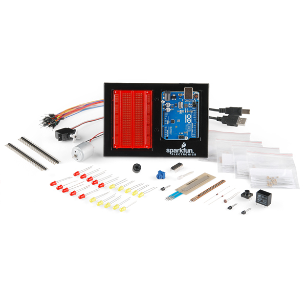
zOMG! This kit has all the things! It includes the Arduino Uno R3, the new and improved baseplate, and all the sensors you can shake a stick at. The SparkFun Inventor's Kit for Arduino is a box of goodies to get the very beginner started with programmable electronics. It includes all the bits you need to build a series of basic circuits, no soldering required!
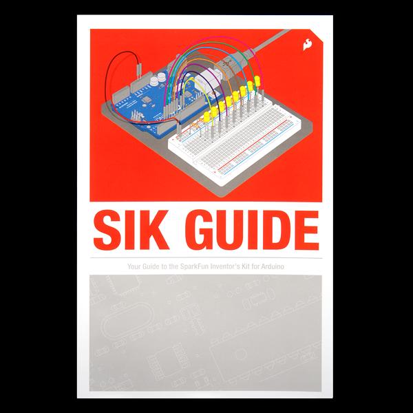
On top of that, we've created a brand new and improved edition of the full-color SIK manual! Updated graphics, code revisions and in-depth instruction have been added to make learning basic electronics even easier! Make your way through the example circuits and you'll learn all about:
- Blinking LEDs
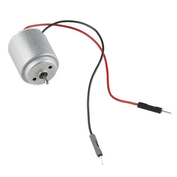
- Controlling a toy motor
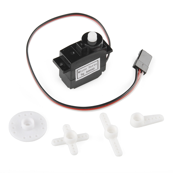
- Controlling a servo
- Making (bad) music
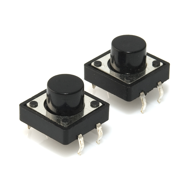
- Responding to buttons
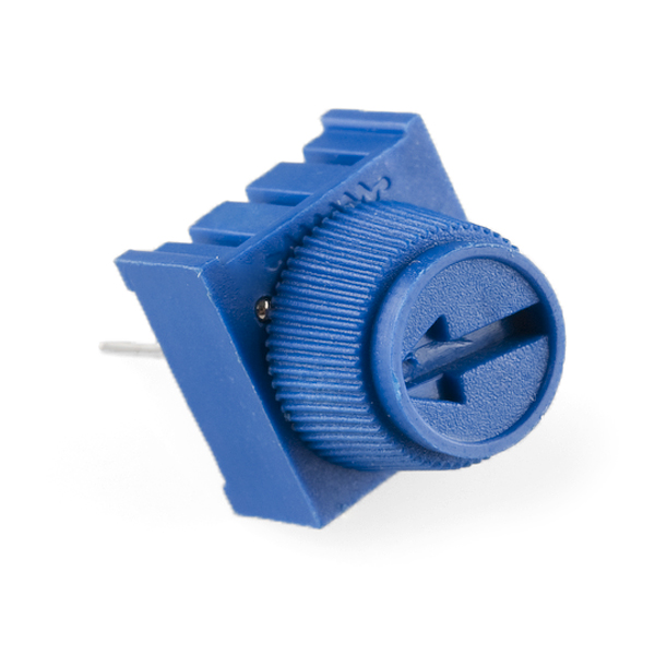
- Twisting a volume knob
- Detecting ambient light
- Reading temperature
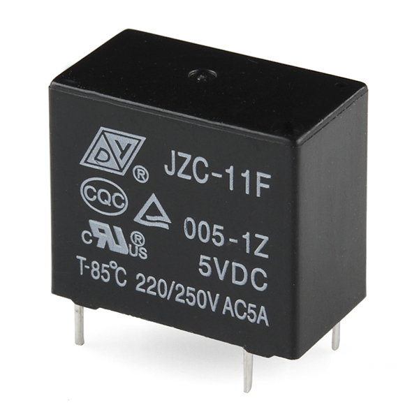
- Controlling big devices
- Mixing LED colors
More!
Once you've mastered the above concepts, you'll be ready to design and build your own circuits, so why not get started now?
Note: No soldering required. We recommend this kit for beginners ages 10 and up.
Documentation:
- SIK Guide
- SIK Review
- SparkFun Education Site
- [SIK Example Code](http://cdn.sparkfun.com/datasheets/Kits/SIK Guide Code.zip)
Replaces:KIT-10173
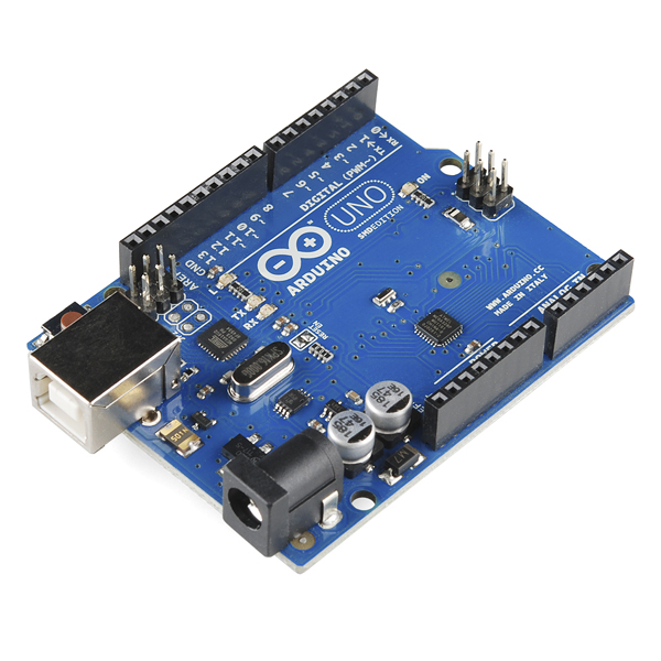
- Arduino Uno R3
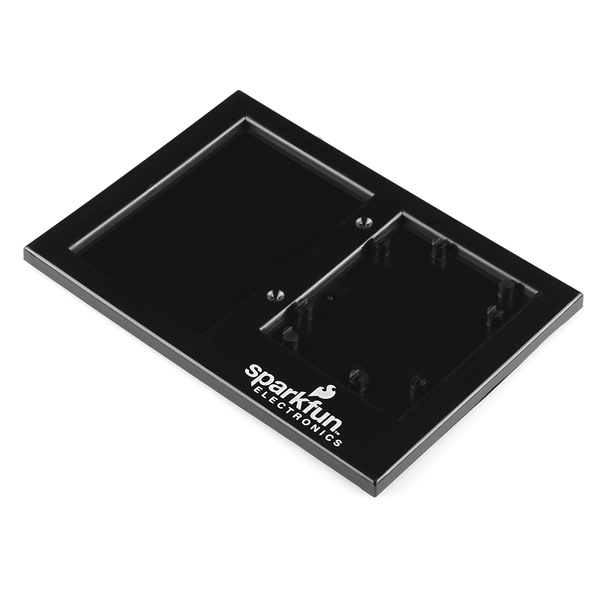
- Arduino and Breadboard Holder
- New and Improved SIK Manual
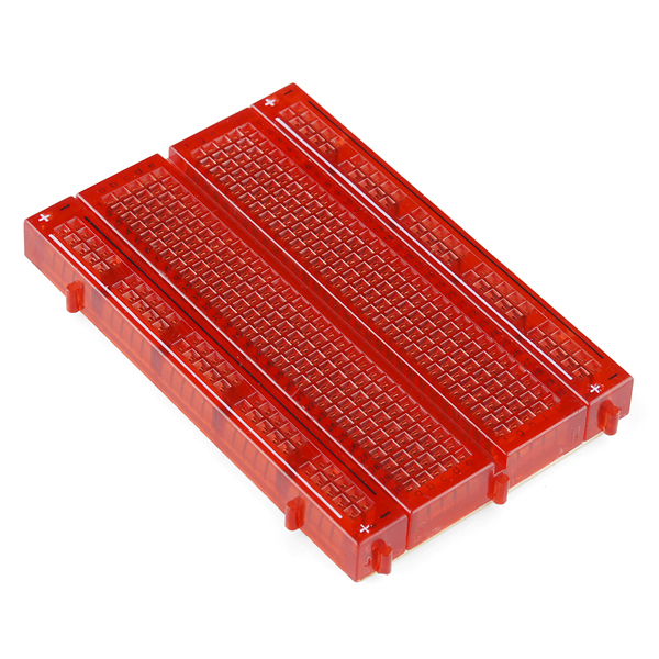
- Translucent Red Bread Board
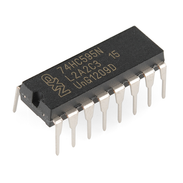
- 74HC595 Shift Register
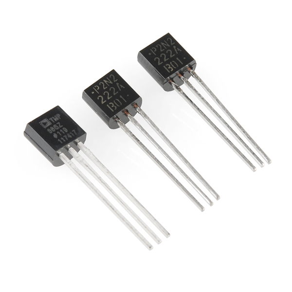
- 2N2222 Transistors
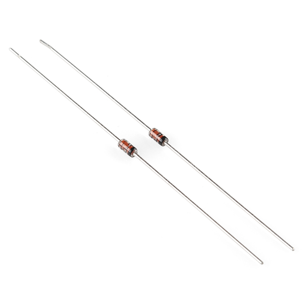
- 1N4148 Diodes
- DC Motor with wires
- Small Servo
- 5V Relay
- TMP36 Temp Sensor
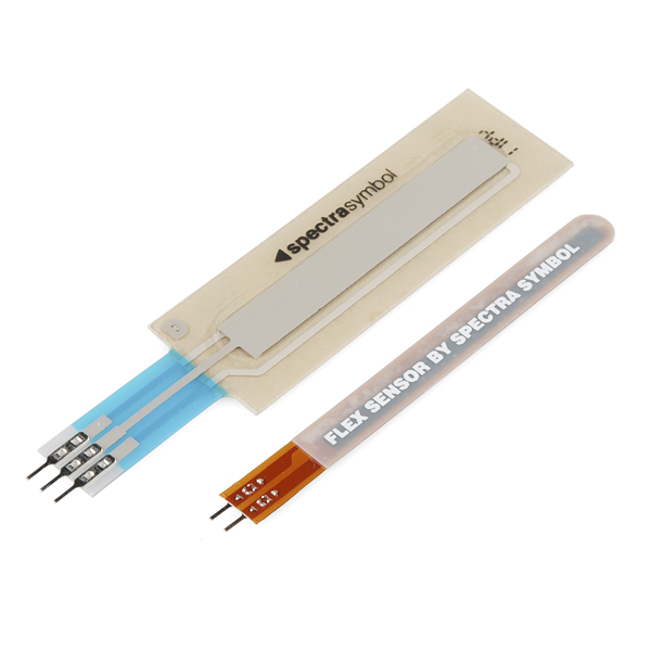
- Flex sensor
- Softpot
- 6' USB Cable
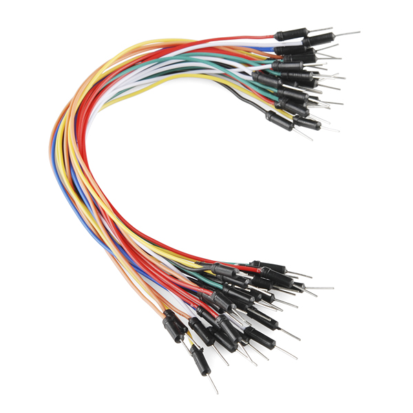
- Jumper Wires
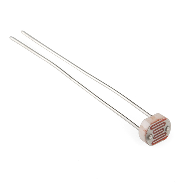
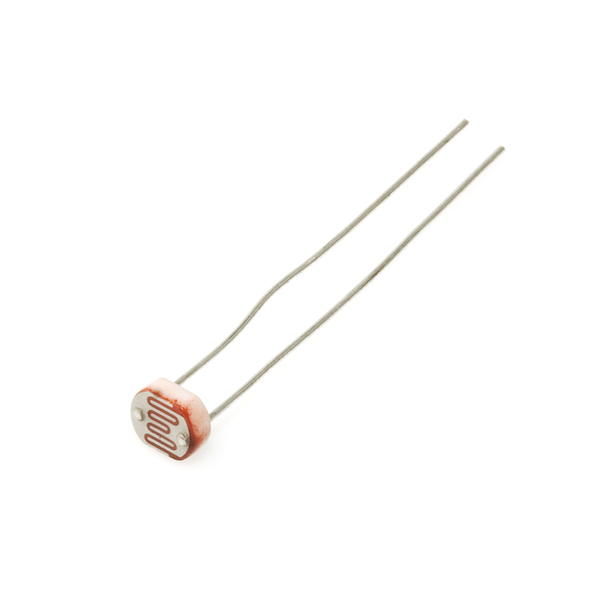
- Photocell
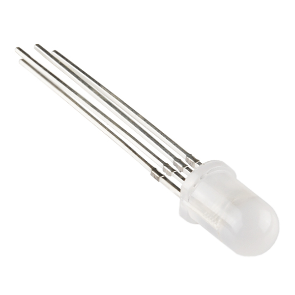
- Tri-color LED
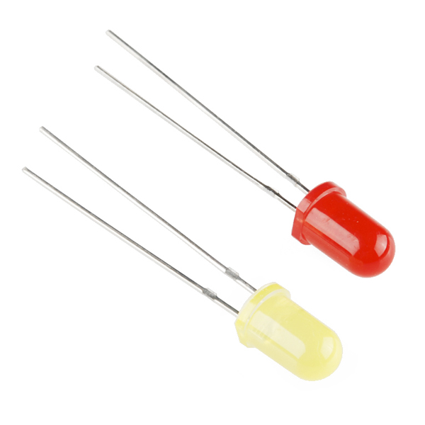
- Red and Yellow LEDs
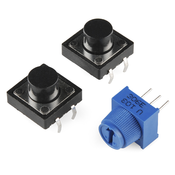
- 10K Trimpot
- Piezo Buzzer
- Big 12mm Buttons
- 330 and 10K Resistors
Comments
Looking for answers to technical questions?
We welcome your comments and suggestions below. However, if you are looking for solutions to technical questions please see our Technical Assistance page.
Customer Reviews
No reviews yet.
Gad, I really do not like the red breadboard. Perhaps I'm too old, but I can't see the black ink. I wish that they had a white one like the one in the book. Because I could not see the board layout, I put the board in upside down, with regard to the way that I installed the Arduino on the holder, i.e. to match the pictures in the book. Now I am worried about trying to remove the board; I tried to pry with a small screwdriver, but the board did some strange flexing, so I stopped.
Cool! But we still want the kit WITHOUT the Arduino! :)
I bought this a few months ago and it's gold! Easiest way to learn how to use an array of simple sensors and actuators. I already owned an Arduino, and there's nothing wrong with having another as a spare or to use in a simultaneous side project.
deleted by author. (I see there's a v3 board now.)
I found a typo in the guide. On page 24, the description says the potentiometer changes the brightness of the LED. It should say it changes the blink rate. (And pin 13 isn't a PWM pin on the Uno so it couldn't change brightness anyway, unless you can use code to fake PWM on that pin.)
I just finished using this kit for an intro course for adults. I'm coming from another uCon platform.
Feedback from students:-------------------------------------------------
Nice mix of sensors and they are high quality
Material covered in guide is a good selection of the core commands.
Price was fine, $100 seemed to be the perceived point of becoming expensive.
Red plastic breadboard is impossible (I heard this about three times per meeting). I was stuck handing out white breadboards from my pocket.
For buzzer, the software has 2 pair of synchronized arrays. One represents the notes of the song to be played and the other the notes of the scale for look-up of letter to frequency. It was confusing. Second one would be a good place to introduce the switch command.
Printed guide has several problems in design: - page numbers are printed white on light gray - code for discussion is printed as yellow on white. Both of these are considered by professional designers as the most difficult to read of all combinations. - not all pages are numbered
The code for the soft pot that creates rainbow is not well explained. The objective is clear but not the math.
The overhead drawings do not add much, given that the Fritz is so clear. In some overheads parts are obscured and in one the graphics software left the jumper looking like it went to the wrong place. Use that space instead to make the intro text large enough to read.
I noticed a lot of students did not use the printed guide because the PDF was so much easier to zoom.
(I told them to disconnect power when changing hardware.) It is tedious to unplug USB then replug and check for com port. The alternate to pull jumper from Arduino 5v to bb is also a drag. It would be great to have some kind of slide or toggle switch to mount to the base that would cut the power between Arduino and bb.
The jumpers from Arduino to bb rails for 5v and ground are always red and black. But also, as much as possible, jumpers from components to the bb rails 5v & gnd should be red and black to emphasize that at this point the circuit is now grounded. (I understand the advantage of having a different color for every jumper to make the direction more clear, so I could go either way on this one.)
Code is verbose with comments and thus hard to follow the commands. (this may be my fault - is there a show/hide comments option like in Eclipse?). An alternate set of sketches that are minimum comments would be useful. (I made these and can share.)
And I'll add a few: ====================================================== When there are independent circuits (connected only by software) it would be better to have a schematic where they are drawn completely independent, not sharing a ground. Not being real experienced with schematics, some students saw all components connected in the schematic and did not always get that the output (LEDS) were only connected through software to the control circuit (relay or transistor). Keeping the two circuits physically as far apart as possible on the bb would help to lock in the idea.
It would be a big help to have a section at end of each project with a few additional modifications or exercises to keep busy the quicker students (I had technicians and EEs in the class). I made up some exercises but I would feel more sure if the solutions had been checked by a more experienced coder and tested by several other instructors. Similarly, it would be great to have a page at the end with a dozen brief descriptions of integrated projects to try; the solutions could be somewhere on-line and even include pointers to related SparkFun products. One of the ways to keep everyone happy is to have lots of exercises at different levels.
It would be great to have a level 2 packaged w/guide. Students were asking about: LCD display, SD holder, EEPROM, prototype shield, PING, real time clock, 7 seg display, accelerometer, motion detector, darlington, stepper motor and digital pot. I'd like to see concepts of communications (SPI, I2C,parallel), organizing data for logging (2D arrays), more complex output to SerMon (graphs), working with shields. Sounds like maybe a Level 3 is in there. Many students asked about way to play real sound (MP3, WAV) to real speakers.
The SIK replacement parts kit is a great idea, but should have all the parts except Arduino, base, bb and jumpers. A relay didn't work and a few parts were lost. I felt sort of responsible and replaced from my parts.
I had to explain the abbreviation on the back cover of the guide.
Next class is in a few weeks and I will probably have more student feedback. In the meantime you can see the website for the course here: https://sites.google.com/site/20130624arduino1aae/home
I know this is SparkFun site, but I am scheduled to teach this course a half dozen times and will probably try some other brand's kits before final selection for ongoing sessions. There may be ideas there that can be brought into the SIK.
I'll keep reporting back with new experiences.
This is amazing feedback! Thank you John! We're parsing it and will roll with as much as we can.
Any chance of getting notified when there's a new version of the kit that accounts for some of John's feedback? In particular, a kit with a white breadboard instead would be nice. I'm a COMPLETE beginner, and want to use the kit to work through as a set of science lessons/projects with my son, so I want to make sure I get the right thing. And I'm willing to wait if an updated version of the kit would be available soon :)
Wow, thank you for all the great feedback! If you do have additional feedback, please email it to techsupport@sparkfun.com. They can generally disseminate the information quickly to the proper departments to make sure your comments are seen (and not lost in the comment section on the website), and also help you with any missing parts your kits may have had.
The diode polarity is still backwards in circuit 13.
The guide has a bug in the motor circuit 12 on page 64. The original version had a 10k resistor, which brought the affects of this bug out even more. This version uses a 330 resistor, which appears to work, but still cuts the full use of PWM.
Pin 9 should run directly to the BASE of the transistor and then a 10k pull-down resistor should be used running from the same (PIN9/BASE to Ground). See: http://bildr.org/2012/03/rfp30n06le-arduino/
The way it is setup on page 64, a 330 resistor runs between Pin 9 and base.
I'm new to this, but interested in a kit. The SIK sounds great but is on backorder. If I get the Arduino+LabView kit and the SIK manual plus a servo, can I pretty much get started? Thanks anyone for comments! BTW, love everyone's helpful comments, you guys have a nice community going.
great kit except for red translucent board which made it had for my 70 year old eyes to see the lead in wires, solid white board much easier to see
More Circuit #3.ino questions Void showSpectrum() ... { showRGB(x); // Call RGBspectrum() with our new x ... Is that really calling RGBspectrum, where is it?
Also you have comments about mainColors() and showSpectrum() sandwiched between them in void loop(). A bit confusing.
showRGB() is the last function in the code, after the RGBSpectrum code. As for the descriptions, there are comments before each function as well as in the loop function when they are called. Because the loop function is so short they work ok there, but this is an easy way for beginners to understand what's going on without having to hunt down the functions. If you have any other questions feel free to email techsupport@sparkfun.com
Circuit #3.ino
// This variable controls how fast we loop through the colors. // (Try changing this to make the fading faster or slower.)
int DISPLAY_TIME = 100; // In milliseconds
What is this, and where is it used? The only time that I see it in the sketch is what i pasted above. As best as I can tell, it gets typed and then forgotten about.
~DN
Is this kit the best way to have a start with Arduino if I already have most of the components (resistors, leads, etc.)? More importantly, have all the glitches mentioned here in this thread been taken care of in the guidebook yet (if not, when)? Also, there is a discrepancy between the picture of the UnoR3 board on this page and the picture of the new Uno R3 board on the Arduino website. Does this kit truly have the most up to date board?
The errors in the guidebook are still in the process of being fixed. They should have a new guide uploaded online pretty soon. I checked with some of the people working on it they expect to have it fixed soon!
The kit does have the most up to date Arduino Uno. The only difference is that Atmel is moving their production more toward surface mount ICs as opposed to DIP packages, so we have more of the Arduino Uno R3s with surface mount versions. Besides that changed package, the board should be the same as the PTH version as shown on the website for Arduino.
Circuit #3 -- the pictures in the SIK Guide (p28) show the 3 color LED staring from flattened edge of the flange as [blue, green common, red). However the comments in the code (lines 15-17) say:
Starting at the flattened edge of the flange on the LED, the pins are ordered RED, COMMON, GREEN, BLUE.
Which is it?
Ah, and looking at the picture on p28 vs the picture on p29, the flat edge of the LED flange is going the opposite direction in the schematic.
Looking inside the LED I would say that p28 is wrong.
The Troubleshooting section for Circuit #5 (Push Buttons) indicates that the experiment contains a fading feature in addition to the on-off mode. Searching within the Circuit_05.ino file in the SIK Guide Code file (downloaded from the SIK Example Code link in the Documentation section above), I was unable to find the example code for this feature.
The schematic for Circuit #6 (Photo Resistor) indicates that the +5 V supply should be connected to a terminal of the photo resistor and a 10-kOhm (Brown-Black-Orange) resistor should be used in the voltage divider. However, the "angle-shot" and overhead view of the breadboard show the +5 V supply connected to a terminal of the static resistor in the voltage divider. In addition, the top-down view of the breadboard shows a 1-kOhm (Brown-Black-Red) resistor instead of the 10 kOhm.
Reference: SFE03-0012-SIK.Guide-300dpi-01.pdf (downloaded from the SIK Guide link in the Documentation section above)
Great eyes, and thanks very much for the bug report! We're currently updating the guide and will make sure these fixes are included. Thanks again!
Code for Circuit #4 has some bugs in the randomLED() function. delaytime should be delayTime, digitalWrite is misnamed in a few places. Also, marquee() function is missing ledPins[].
Was this a test?
The real test is Circuit #13. If page 69 of your copy of the guide is anything like mine, it will be an exciting race to see which blows first, the diode or the transistor. Pay careful attention to the polarity of the diode (it's wrong in the breadboard diagram in my copy of the guide.) The cathode (black band) should be on the "+" side of the relay coil. The connections list on page 70 is also wrong (in a totally different way.) The schematic on page 68 is correct.
Blllaaargh .. been trying to figure this one out for two days now!! Hooray!
Thank You, I was able to make it work just by putting the diode like you suggested!
Thanks for indicating the problem with this circuit. I just bought my kit last week and it was driving me crazy why my circuit didn't work.
Thanks for pointing this out. This was the only circuit that gave me problems and it's nice to finally have it built correctly.
Great catch on the diode polarity, thanks!
The kit I purchased last week still had this error in the printed book as does the .pdf linked on this page. I presume this is why the diode was getting so hot and only the yellow LED was lighting up?
Yes, you pass! =) Thanks very much for the bug report, we've fixed the errors (an old file got in there by mistake) and put up a new zip file. Delete the old files and reinstall the new ones per the instructions in the guidebook.
Thanks again and please let us know if anything else doesn't work right.
I just downloaded the zip file... and I noticed the same errors reported by "Member #365381" are still there.
I just downloaded it from both this page and the link in the manual, and it's the new version - are you sure you deleted the old files first? You can try opening Circuit 4 directly from the .zip file to be sure.
This is awesome guys. What is the weight of the kit. The price of ship is based on the weight ?
Will the new SIK Guide (in print) be available for purchase separately for those of us who bought the old kit?
Did you see that there is a link at the bottom for the guide?
first!!!!!!!!!!!!!!!!!! i must say, its not "shake a stick at", its "poke a stick at"
Must be regional, because it was definitely 'shake a stick at' where I grew up.