- Home
- Product Categories
- Battery
- SparkFun Power Cell - LiPo Charger/Booster

SparkFun Power Cell - LiPo Charger/Booster
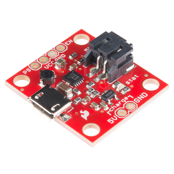
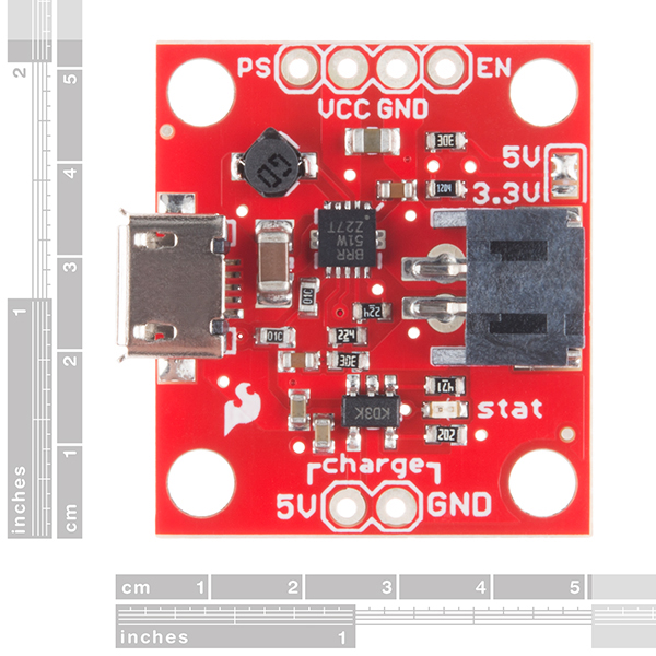
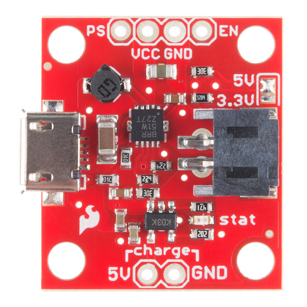
The PowerCell board is a single cell LiPo boost converter (to 3.3V and 5V) and micro-USB charger in one. The board comes with a JST connector for a single cell LiPo battery, a micro-USB connector for the 5V charge input, and selectable 3.3V and 5V output pins (labeled 'out'). There are also two charge pins broken out (labeled 'charge'), so you can use another 5V power source to charge the batteries, if you don't have a micro-USB cable.
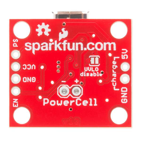
We've also broken out the power-save and enable pins, so that you can have full control of the switching regulator. Keep in mind, if you keep your battery connected to the Powercell, it is recommended that you disable the switching regulator (pull EN low) in order to prevent the battery from discharging and reaching the under voltage cutoff on the battery itself. There is also an under-voltage lockout on the Powercell board which is tied to a solder jumper so that you can disable it if you like.
The boost converter is based on the TPS61200 from TI and has solder jumper selectable 5V and 3.3V output, and an under voltage protection of 2.6V (which can be disabled via solder jumper on the back of the PCB).
Note: This board does not have reverse polarity protection, so please be sure to recognize the polarity of your connections!
Note: When you are finished charging your battery, it is recommended that you remove the battery from the Powercell, since the charge will slowly drain without proper management. Check out the Hookup Guide in the Documents section below to learn how to control the charging and regulator output.
Replaces:PRT-10300
- MCP73831 Single Cell LiPo charger at 500mA
- TPS61200 Boost Converter
- Selectable output voltage 3.3 or 5V
- 5V @ 600mA max
- 3.3V @ 200mA max
- Undervoltage lock out at 2.6V (with disable jumper)
- Quiescent current, less than 55uA
- JST connector for LiPo battery
- micro-USB connector for charge power source
- Inductor: 4.7uH, 1.2A Sumida CDRH2D18
- Over temperature protection
- 1.03 x 0.95"
- Schematic
- Eagle Files
- Tutorial
- Datasheet (MCP73831T)
- Datasheet (TPS61200)
SparkFun Power Cell - LiPo Charger/Booster Product Help and Resources
No Load Consumption
When the battery is attached and there is no load, the power boosting circuit will still draw around 7.32 mA.
If you ground the (EN) enable pin, the circuit will turn off and pull around .42mA with no load.
Core Skill: Soldering
This skill defines how difficult the soldering is on a particular product. It might be a couple simple solder joints, or require special reflow tools.
Skill Level: Rookie - The number of pins increases, and you will have to determine polarity of components and some of the components might be a bit trickier or close together. You might need solder wick or flux.
See all skill levels
Core Skill: Electrical Prototyping
If it requires power, you need to know how much, what all the pins do, and how to hook it up. You may need to reference datasheets, schematics, and know the ins and outs of electronics.
Skill Level: Competent - You will be required to reference a datasheet or schematic to know how to use a component. Your knowledge of a datasheet will only require basic features like power requirements, pinouts, or communications type. Also, you may need a power supply that?s greater than 12V or more than 1A worth of current.
See all skill levels
Comments
Looking for answers to technical questions?
We welcome your comments and suggestions below. However, if you are looking for solutions to technical questions please see our Technical Assistance page.
Customer Reviews
4 out of 5
Based on 14 ratings:
2 of 2 found this helpful:
Pretty sweet little device
Works well. Easy to get working. I combined with an LTC2955 power button controller to enable the TPS61200. Seems to charge fully and consistently. Provides good power at 5V.
9 of 9 found this helpful:
This was awesome years ago, but now it's almost obsolete ...
I really can't figure out why Sparkfun is still selling this little guy for $20 bucks. Adafruit has a PowerBoost 500C for $5 less that has a entire load of features this one does not have. I can't recommend this since good quality manufacturers are making similar products that actually has built-in protection that this one does not. You'll spend more on this one and very easily burn it out.
Sparkfun should really redesign this with the TPS61090 boost converter from TI that Adafruit uses.
If this little guy was more competitive in it's market it should be closer to $10. There's no protection on this thing and I've blown the one I had already. If it used a better chip it would have reverse polarity protection, a higher current rating, and even thermal protection.
3 of 3 found this helpful:
It works perfect,
I had to get a replacement due to the USB connection coming loose on the previous one. I have since then reinforced the mounting with hot glue. Hopefully this will last longer. The Size and function is still its best features!
USB jack broke off
On first use, plugged in USB cable and the jack broke off the board. Looked at the SMD pins and they were intact, like they were barely soldered in place. Instead of the micro, should use the mini connector, which can be mounted more solidly.
really nice thing with great function
it works very well, charge with 500mA and disable the step-up at 2,6V to protect the battery, to enable you have to charge the battery and the normal recreation does not enable, this protect your battery very well
Does what it claims
I've been using this with the 2000mAh lipo battery, and it works flawlessly. It could be improved by adding a pinout for the battery voltage, and I'd give bonus points it it offered a 3.3V rail, but alas; it works as advertised.
Seems to be working corectly.
But a few suggestions: 1) Add pin out to access the charge led. 2) If the battery is disconnected and charge power is applied, the charge led is lit. This makes you think the battery is connected, which it is not. 3) Add a Fet that saturates when charge power is applies to pull the EN signal low. This will force the Vcc off when charging. Also have a way of disabling this feature for those who want to have Vcc on when charging. Other than this for $20 you can't go wrong.
Very good charger/booster
Very good product and very small, fast delivery. Working perfectly as the description is. The only thing missing is the un-interruptable power supply (UPS) system.
Saved me time
I used it along with your 2000mAh LiPo to turn a decorative dragon box into a small rechargeable portable power supply. Only addition I would have wanted was to have the 3.3-5v selection pads be jumpers.
Not perfect
A few issues with mine: - Pulling EN low is still outputting ~ 1V on the output. - Setting voltage jumper to 3.3V is only outputting 3.18V, not the expected 3.3V - Charge current is ~ 50mA, not the stated 100mA Is the device broken or is this to be expected?
I would suggest getting in touch with our tech support team, they should be able to help you out!
Great little part!
Using it currently for a wireless remote, worked perfectly for battery management. This with a Pololu power switch I can charge and cut off at a safe voltage as well as charge when necessary.
Works great for my needs.
I used it to power the flight computer in a high power rocket. Supplies enough current to power my arduino board, GPS, 900MHz XBee, and still fire ejection charges without causing a reset. I also like that the enable pin is broken out so I can use a jumper to arm/disarm my flight computer.
The best power management device !
I love this thing. Best power management device ever. Also a very good reference design if you want to design your own custom device with different specs.
-------------------- Tech Support Tips/Troubleshooting/Common Issues --------------------
Coin Cell
I tested the PowerCell [ https://www.sparkfun.com/products/11231 . The coin cell was not able to power a 5V Arduino. This would probably be the same for other boost converters. The output power of the coin cell is probably be too low to be boosted for the boost converters. You would need a battery that is able to output more power. It would be better with a LiPo battery with nominal 3.7V.
... I may be a bit behind.. but ya'll may want to review/revise your schematic for this one. The two pins for Enable and Power Save are connected to the VBATT net, instead of to the IC... ?
Good eye! In Eagle, labeled nets are "invisibly" connected to other points in the schematic with the same label, even if there's no line there. So EN and PS do connect back to the chip. The schematic could be clearer in this regard (should we make a schematic with no lines and just labels?). Sorry for the confusion, thanks for asking!
Is it ok to have the battery always in here? As in, while charging, under load, on standby.
A few issues with mine: - Pulling EN low is still outputting ~ 1V on the output. - Setting voltage jumper to 3.3V is only outputting 3.18V - Charge current is ~ 50mA, not the stated 100mA Is the device broken or is this to be expected?
Can i use this to charge for 200mAh lipo battery ? (Use 5v Power supply) I read the description, the charging current is 500mAh. I worried excess charging current allows. Thank for support me :D
Please help me :)
I wouldn't recommend charging a 200mAh battery with this board as is. You would want to replace the 2k resistor attached to the PROG pin, to ~5k to achieve a 1C preferred charge rate.
Has anyone had problems with the EN pin not turning the regulator back on after being pulled to ground and then back to Vbatt?
For me pulling EN down to ground works like a charm and shuts off the regulator. But then when I pull it back up to vbatt (via a dpst switch) it doesn't come back on. Only disconnecting and reconnecting the battery gets it running again.
Any clues what might be going wrong here?
Isnt it easier and cheaper just to purchase a powerbank. that way you have battery and booster circuit. You can get 2600mAh for 1 dollar on ebay.
I've tried a number of powerbanks from China thinking just the same thing. And the reality is that you don't know what you get. Often these powerbanks have charge control and load-detection circuitry built-in which makes them useless for powering low-power projects and unpredictable in powering higher power ones.
With the sparkfun unit there's no surprises. It just works.
I'd like to see one of these with the D+ and D- pins broken out, so the battery can charge without requiring an additional USB connector, for USB-driven battery-backed devices.
I suppose it'd be possible to simply use the 5V in with another USB breakout board, but that seems somewhat inelegant given that there's already a USB connector onboard.
There's a good reason not to do that: signal integrity on the D+/D- lines.
It might work, some or even most of the time, but in the end, it would be a feature that invites trouble in to stay. It's a far better solution to connect the USB to the device that has USB connectivity, and then pull the 5V off that to feed the Power Cell (or whichever charger you're currently using).
I'll second that - let it be a bit wider, but with D+ and D- broken out. Currently, the capacitor in front of micro USB connector prevents using these pins directly, and de-soldering the connector to place it on separate board is not so nice variant.
Sparkfun, can you please start breaking out D+ and D- on your chargers? Would be great. Smaller would also be nice.
Should I try to use this in a solar charging system? What happens when the input voltage drops below the minimum operating voltage when using the alternate 5v source from solar power? Side q, is using a regulator (7805) appropriate, or is there a better option for regulating the volts from solar as the 5v input for charging. Thanks anyone.
If you put a large cap (~10,000 uF) across the solar panel it will work much better for charging. Otherwise the current will porpoise up and down and the charger never really gets to go through it's cycle without interruption. Adding the cap smooths out the current and stabilizes the whole system, making it much more efficient.
Note - just use a standard electrolytic cap. Supercaps do not seem to work well for this.
+1
I am wondering this a LOT too!!!
Can the power cell be used as a UPS? If the lipo is fully charged, yet the Powercell stays connected to Solar and micro-usb(wall-adapter), will the load (i.e. Arduino Uno) in this case draw current from the lipo, or instead directly from the wall adapter, preventing the lipo to discharge? I'd like to minimize unneccesary (re-)charge cycles as long as the unit is connected to the wall adapter and solar panel (in order to keep battery life at a maximum), and I'd like the 5V/lipo booster to jump in the moment the power provided by the micro-usb (wall-adapter) turns off. So ideally, only drain the lipo in case the wall adapter is off (i.e. mains is gone). Many thanks!
Hi, I have two questions 1) Can use the TPS61200 booster circuit while charger is connected means the USB is connected and charging the battery and simultaneously I am using the booster circuit to power on my circuit. 2) I have seen some comments mentioning that booster circuit continues to drain the battery if OUTPUT 5V/3.3V is not connected to any load, How much current it is ? So will it damage the battery ? How can I change the UVLO setting to set to 3.2V ? I think it is quiescent current I am talking about. My system doesn't have the switch so I cannot use EN pin to switch the OUTPUT disable to save the battery. 3) Is there any indication if battery is fully charged ? Regards Bishan
It emits a low-volume high frequency tone while charging and it is giving me a headache. Anyone else experiencing this?
Maybe this could be the coil, there is not other possibility!
You've broken out PS and apparently pulled it high. That means "disabled" for PS, according to the 61200 docs, but contradicting what you've written in the tutorial (which is saying that both EN and PS are enabled by default). You also don't discuss what we might want to do with PS in your tutorial. Since you've bothered to break it out, you must think that some people would be interested in using it... any advice on why/how? Are most people safe not using it at all?
Power Save Mode The Power Save (PS) pin can be used to select different operation modes. To enable Power Save mode the PS pin must be set low. Power Save mode is used to improve efficiency at light load. If Power Save mode is enabled, the converter stops operating if the average inductor current decreases below about 300 mA and the output voltage is at or above its nominal value. If the output voltage decreases below its nominal value, the device ramps up the output voltage again by starting operation using a programmed average inductor current higher than required by the current load condition. Operation can last for one or several pulses. The converter stops operating once the conditions for stopping operation are met again. The Power Save mode can be disabled by programming a high at the PS pin. In Down Conversion mode, Power Save mode is always enabled and the device cannot be forced into fixed frequency operation at light loads. The PS input supports standard logic thresholds.
and looking at the figures on the 61200 docs it looks like it smooths out efficiency at low currents (<300ma). since i plan on using higher currents anyway my application is irrelevant.
Charger board very hot! I have this charger connected to a 1 cell battery (sparkfun prt-08484). I have the enable pulled to ground. I am charging the battery through the board by connecting the micro USB to a wall charger. The whole board got very hot. Tis does not seem correct. Cn anyone tell me what I adoring wrong and how to fix it?
Can you explain "The micro-USB charger uses the MCP73831 and allows you to charge 3.7V LiPo cells at a rate of 100mA max. If you want to charge at a faster rate, you will need to connect a separate power supply to the pins labeled '5V' and 'GND' under the label 'charge'. "
Your schematic shows A) 2KOhm on PROG, which should mean a 500ma output charge current, and B) the USB and pad inputs tied together.
I think Sparkfun might be referring to the fact that USB specification states that a USB slave device can't draw more than 100ma without first enumerating the host and requesting it.
Although many controllers aren't spec compliant and will let a device draw whatever it wants.
I NEED a version of that that can handle Uninterrupted Power Supply (UPS). Like this one but with your great Open-source policy, I won’t buy it if it’s not clearly and proudly open source. https://www.adafruit.com/products/2465 For a more in depth explanation click on the link .
I NEED a version of that that can work as an Uniturepted power supply (UPS) like this one but with your great opensource policy, I won't buy it if it's not clearly and proudly open source. https://www.adafruit.com/products/2465 more in depht explanation => it need to be like that: Since the built-in battery charger has load-sharing, it will automatically switch over to the USB power when available, instead of continuously charging/draining the battery. This is more efficient, and lets you charge-and-boost at the same time without any interruption on the output so its fine for use as a "UPS" (un-interruptable power supply).
Can this charge at a higher rate than 100ma if supplied through the 5v port?
What is JP14 and JP13 for ? on the shematic ? on the booster circuit, thanks a lot ;)
I'm surprised there is no breakout for VBATT. This would be useful for a soft power switch or for battery voltage monitoring. Also a breakout for the STAT pin would be useful for LED indication on the outside of a project.
This modules are awesome... but I miss a feature: You should have provided a pin to weld an external charge led. Is difficult to remove the onboard led, in order to weld microwires to an external led.
is there a fritzing part ?
I'd like to charge two 2.7 V ultracaps in series (for backup power) and feed an Arduino Uno (with the USB port) with a solar panel. The ultracaps are shortcircuits when they no charge at all then I need to limit their current because otherwise the Arduino shut down until the ultracaps raise their voltage. Is this product useful for that?
@Sparkfun: Have you guys ever considered re-drafting this board to fit a cell holder as well? Something like a 14500 Lipo (AA size) or the 18650 cells many folks might salvage from old laptop batteries? Having this board prefitted to a holder, or even just mounted metal contacts for the cell would be awesome!
Not happy with the product.
Already broke 3 of these units in 2 days.
1) The micro usb basically falls off just by looking at it. The reason is that its not a through usb that solders on the bottom of the USB, but is basically kept on by 2 tiny solder drops on the top. Cant get back to working order
2) the battery connector jams right in and the only way to get it out is to break the housing. (Solution is to shave off the groves on the battery connector)
3) en grnd vcc holes are not correctly situated if you are to believe the manual and you are trying to use an SPDT switch. The EN port should be between vcc and ground. Otherwise you have to break off one of the stems and solder mid connector to en and one of the side connectors to ground.
Maybe I am wrong about part 3 buy I never got a response so this is my presumption.
All in all if you are buying this, make sure you are VERY gently the USB port
Where could I find BOM for this product? Thanks anyone
Email techsupport@sparkfun.com and they should be able to get that for you.
Anyone know how to get the JST connector out?
Put something strong and small through the slits in the port and pry the connector out from the inside. When you have it out - cut off the plastic bumps on top of the connector with a hobby knife and it'l be much easier to remove in the future. After doing that mine still holds in pretty well, but it's at least now much easier to unplug - using tweezers.
While LiPo batteries have a voltage of roughly 2.5 to 4.2V, they drop off fairly quickly after they hit 3.5V, which means using this part in a 3.3V project will run the converter in the extremely inefficient (~75%) step-down region for most of the time. Consequently, I wouldn’t recommend using this part for 3.3V projects that are LiPo-powered.
Most designs I’ve seen actually just use a buck converter to step-down the voltage – when the battery voltage drops below 3.3V, the converter will track the input voltage. This may seem counter-intuitive, since you don’t “squeeze out” all the juice in the battery – however, the increased efficiency of the buck solution means you get longer battery life overall.
One article I read indicates at 300 mA output current, a buck converter got 9 more minutes of battery life than a buck-boost converter of similar configuration: http://www.eetimes.com/document.asp?doc_id=1273123&page_number=3
Obviously, if you’re building something with ultracaps or other low-voltage stuff with UVLO disabled, this is a great part to use. And it definitely shines at 5V output – I’d just stay away from using it in a 3.3V configuration with LiPo batteries.
MORE CURRENT!!
Come on SF, throw us a bone. Give us something we can put between a 3.7v 2Ah LiPo cell and our Raspberry PIs, beaglebones, etc. I’m willing to pay for it, it just doesn’t exist
I have a 3 cell lipo battery. Will this work? Can someone show me a product that will charge a 3 cell (each a 3.7 v and 2000mah)
Can I use this circuit to charge multiple Lipo's in parallel? (All the same size, 1000mah). Thanks
As Member #126605 already mentioned, tying EN and PS via 10k Ohm to VBATT is not that good of an idea. A much higher resistor like 500kOhm should do it, or even better, tie the inputs via resistor to GND and add a jumper to pull it high when enabled.
I observed a strange behaviour when starting up an Arm controller board (OLinuXino imx233): I had short voltage dropdowns to 4V or so, which led to continous restarts. Then I removed the C2 100nF cap at UVLO, which removed this behaviour. Maybe my findings help sombody and a next revision removes these flaws. I would expect a reduced responsiveness to battery voltage change with C2 installed, but the contrary seems to be true. TI datasheet (which is available in a more recent revision than here) doesn't mention anywhere the need for filtering UVLO input.
Why is the undervoltage lock out at 2.6V? Shouldn't you stop discharging lipo cells at ~3.6 to avoid damage?
After the low voltage lock out, is it safe to leave the battery in "indefinitely"? (ie, without further discharge/damage)
can i use this with a 3.7 lipo and a COM-11288 heating panel or with the regs overheat?
A word of warning for those thinking of using the STAT line for both states. The "CHARGING" LED is connected between VIN and STAT, the "CHARGED" LED goes between STAT and GND. When the charger is not in use that leaves a couple mA quiescent drain on the battery which might be undesirable for most battery applications....
The USB is limited to only 100mAh in charge? Is not 500mAh?
I put it to charge the computer's USB, after a while, I realized that the "MCP73831" very heated. I thought it was normal because the battery was carrying ... After a while, when I recheck the charger and the led was off, I thought the battery was 100% charged, but was not, after about 15 minutes of use, the battery drain completely, then went on to charge again, and after a few hours the LED still flashing, and the battery never charged!
So? I lost my $ 19.95 on the first day of use?
Sorry to hear you had trouble! Contact techsupport@ with your order number and a detailed description of exactly what happened. They should be able to help you further.
Can I use this to charge the following battery: PANASONIC - PA-LN19 - BATTERY, LI-ION, 1S1P, 3.7V, 2.9AH?? (http://nl.farnell.com/jsp/search/productdetail.jsp?SKU=1900168#accessories)
I'm trying to charge a battery (sorry, no idea how much mAh, because it is permantly covered) via USB connected to my computer, but the red light turns off after a few minutes. Whey I unplug it and try it again it turns on for less time and turns off again. This does not mean that the battery is charged, right? Because when I use the battery it only powers the devices for a few minutes. Any idea what this could be?
I am having a problem with this unit. When a battery is connected, no load is present AND the charge cable is disconnected, the battery is run down to almost 0v. This is terrible for (unprotected) Li-Poly cells, it ruins them and I have a couple of dead cells because of this.
I have checked the UVLO jumper, its open, so one would assume that the under-voltage protection circuit would kick in and stop the battery from draining below 3.6/3.7v? From what I read and heard is that the booster is constantly on regardless of load and this is what drains the battery, BUT shouldn't the under-voltage protection kick in?
I have had to add a switch to disconnect the battery from the charger on my projects when not in use. What am I missing?
from what i can see in the schematic, it should cut out at 2.6 volts
I thought I might be able to power an Arduino Due with this, but am skeptical after giving it a try.
I loaded the "fade" sketch and had an 10mm LED and 220kΩ resister on pin 9, soldered the 3.3V jumper on the PowerCell, hooked up SFE's 6Ah battery, and connected the grounds. The VCC went to the Due's 3.3V pin.
The results weren't good. First, the Due's "L" LED (associated with digital pin 13) was only sort of half-bright, when normally it is full bright with other power sources. Also, the sketch wasn't running. The LED on pin 9 was at full bright. So I pressed the reset button and then LED on pin 9 burned out.
Due's regulator was bypassed using the 3.3V pin, but the PowerCell's regulator should have taken its place. Maybe someone can explain why not. I don't think I can use this to make a LiPo-powered Arduino -- it was kind of an expensive lesson.
I've been thinking about making a portable power bank using this board alone by adding a female usb connector to the output and adjusting the D+ and D- pins with the extra resistors like in MintyBoost3. I was just wondering if the 600mA is enough for some of the modern devices or will it be a problem?? Please also advice if I'm missing something with the whole idea. Thanks
I used a photo Darlington (from NTE) with a 10K resistor pulled high on the collector, emitter to GND, and connected the collector to EN to make my circuit only operate after dark. So, I can charge with a solar panel during the day and run arduino lights at night automatically. I put a switch across the EN to GND connection in parallel with the Darlington so I can switch the whole thing off manually.
I have an Arduino Esplora that I’m going to use this with. If I run a 5V line from the Esplora to the 5V charge pin and also to the Vcc pin, will I be ok? I want the power from the Arduino’s USB connector which will be exposed to be available to charge the battery and when I disconnect it, I want the battery to take over.
I will have a switch to allow me to turn off the system when it is not connected to USB and I know I’ll have to disable this board.
Hey.... Nevermind (as Rosanna, Rosanna Dana would say), I just discovered the landing page and it pretty much answered my questions! Thanks!
I'm A total newbie at this.. so here goes: I have a device that requires 4v minimum. The device will draw a maximum of 1A for 500ms per event. I'd like to power it with a single cell 3.7v lipo. Will the PowerCell work for this app? Thanks!
I plugged my lipo battery into this, and the inductor in the upper left corner started to get so hot that it melted the plastic coating on the board. I quickly unplugged the battery. After measuring with a multimeter, I discovered that the positive and negative of the connector on the board for the battery were shorted together. The battery did not get hot though, only the inductor. What could I have done wrong? Help please
Same thing happened to me, except it turned out that the VCC and GND pads were shorted together, and EN was pulled to ground. Can't seem to wrap my head around it either, the EN pin worked fine on boards I bought previously.
The datasheet for the TPS61200 definitely says I can pull 600mA (figures 1 and 2), just at a lower efficiency of around 50-60%. Is there anything wrong/dangerous with doing this? I don't know why you or the datasheet says 600mA when it can go higher at a lower efficiency (which is okay in my application). I am hoping to pull between 600-1000mA for no more than 2-3 minutes every 15 minutes. I really would love this board as it does the charging and boost converting in one, which is perfect in my application and don't have time to make my own PCB.
Need to know before I purchase. Thank you!
Can I use this with the Polymer Lithium Ion Battery - 6Ah (PRT-08484)? I know that this says to use it for single cell only, but I wanted to make sure. Thanks!
That would be a yes. The 6Ah acts a single cell.
How can i get it to output 5v@1000ma(1A) or more? what could i do?
The TPS IC is only rated to 600mA @ 5V. We don't carry a charger and regulator combo capable of 1A. You will need to combine the battery charger and some type of regulator (here is a linear one that might work for your application).
EDIT: I couldn't find it initially, but we also have a beefy 6A switcher.
The red light will light up even there is no battery connected?
Correct. If you just have USB plugged in and no battery, you should see the red LED on.
There are a few of changes I'd like to see.
VBATT should be available as a pin, both for powering something directly from the battery and for battery monitoring. There is a pad for it but the connection is rather hard to solder to as the hole is capped by the JST connector.
The STAT signal should be broken out for monitoring by a CPU.
I would eliminate the resistor pullups on EN and PS and add a solder jumper from EN to VBATT and another jumper from PS to VBATT or GND. To use either the (dis-)enable or power saving feature, the resistors draw 370 uA each when you ground one of those pins. This greatly overshadows the 55 uA quiescent current.
Otherwise a nice, useful part
Hi I'm using this product with the PRT-00339 battery I disabled the UVLO on this board because the battery has it's own... My application is running high power LEDs so I will typically drain the batteries to the point where the UVLO of the battery engages... The problem is when I plug in 5V for re-charging the charger will not begin until I unplug and re-plug the battery. This is not good because I need the battery to be pertinently connected but also recharge from dead. Is there any trick to fix that?
I am confused.. When I pull the EN low, does the board continue charging Li-po or shut down everything?
Any suggestion so that I can pull low automatically at night? I am doing a solar tracker project.
I was thinking to use this in order to power a 3.3V circuit (no 5V around) from a LiPO battery. My problem is that I need to be able to power my circuit when I have USB connected (and this I think can be accomplished with this board) but also when there is no battery connected.
If I tie (with a piece of wire) the VBUS to the VBATT net (TPS61200 VIN) I'm afraid that I could damage the battery. Is this correct? If yes, any idea of what could be a quick turnaround? Thanks!
I just checked the unit I have received and found that it has 3.2 volts cut-off voltage, not 2.6 as written here. When battery level is below 3.2 volts there is zero at Vcc. That is very good since 3.2 volts is best cut-off voltage for battery I have.
I still curious how that may happen.
OK, I see in the TPS61200 datasheet that there is a hysteresis on undervoltage lockout threshold. So, the possible scenario is following: battery discharges down to 2.6 v, the device turns off, then the battery voltage goes up to 3.2 volts since there is no load.
Am I right?
How much does it weight and what is the effect on the current drawn from the battery. For example if the battery provides 250 mAh what will it be after I connect it to the power cell.
I have a few questions before I order. I'm sorry if they are dumb questions or if I overlooked something but I just want to make absolute sure what I am buying is what I want.
1) What happens when the supply voltage falls below 5V? I see from the MCP datasheet that the minimum supply is 3.75V.
2)I would also like to know what the minimum supply current is. I ask this because I am using a solar panel system as the supply source.
3)Can you recommend a voltage regulator that I could use in conjunction with this in order to supply a constant supply voltage?
4) Using the "charge" inputs as supply, is there any reason I could not charge the battery using this device and discharge it using a load as well?
Thanks
1) As you approach 3.75V the charger will shut off.
2) This will depend on the state of your battery. You should look at the DC characteristics and the performance curves in the MCP datasheet for a complete description on this.
3) There is a switching voltage regulator on this board that can supply 3.3 and 5V.
4) Sure, that is the purpose of this board.
See this tutorial for more information.
I purchased three of these for use with XBees, and moved the solder jumper to 3.3v. Of the three, one entirely failed to work, and another output 4V, destroying an XBee. Purchase this product at your own risk.
Please contact techsupport at sparkfun dot com. You either have defective boards or you are using the boards incorrectly. Tutorial on how to use this board can be found here.
Hi I was wondering if it would be possible to increase the max current output for the 3.3v to around 300mA (as stated in the TPS61200 datasheet)?
You might be able to get away with drawing 300mA@3.3V, depending on what you are powering. But with our testing, in general, reliable operation is around 200mA max @ 3.3V.
Thanks for the answer! But roughly what does it depend on? (sorry hardware newb here)
So how do I get the DRC in batch pcb to accept and not fail the pin spacing (TPS61200)?????? obviously you guys did it. Thanks
Check out the forums as well on the BatchPCB site-there's a lot of great fixes posted from other users for various board errors.
I would contact batchPCB directly, they should be able to push it through. Also, we don't use batchPCB for our red boards.
Do I constantly have to pull en low to keep the battery from discharging of can I just pull it low before I turn everything else off and it won't discharge even without the en pin being pulled low constantly?
Is this product suitable for building a UPS for a Raspberry Pi? I'm thinking of using the Power Cell and a PRT-00339 1000mAH battery to provide my Pi with roughly 1 hour battery backup (hopefully much longer in sleep) in case of failure.
What I'm actually trying to achieve is an in-car solution that sleeps (but doesn't completely power off) the Pi whilst the vehicles ignition is off, providing a quick start-up as soon as the ignition is turned back on. I'd use a 5V 2A regulator connected to the Power Cell, connecting the Pi to the output, as soon as power is applied there should in theory be enough juice to power the Pi unabated whilst charging the battery.
I'm hoping that I can somehow implement a power management system whereby the Pi is put into deep sleep with no ignition power and then woken up when ignition power returns, and hopefully the 1000mAH battery is strong enough to run a Pi in deep sleep + the Power Cell in power saving mode for a few days, although I can envisage jumping up to the 2000mAH equivalent.
From reading this description, the landing page, and the comments, this looks like the board I need to connect a solar panel (PRT-07845), battery (PRT-00341), and 3.3v arduino for an "always on" project out in the woods. The arduino code uses a lot of sleep mode and other power reservation techniques that would allow a stand alone battery to power this project by itself for months, possibly years. I want the power to be as self-sustaining as possible, so I wanted to add a solar cell to recharge the battery daily.
I am concerned because I read the comments below that indicated that the power regulator itself can drain a battery in a few weeks even with no load. I realize that the solar panel will help with recharging the battery during the day, but during winter or long periods of overcast days, I can't have the power regulator sucking this battery dry.
I am a beginner, so maybe I am misunderstanding a concept here, but it seems I need to be able to make up for the draw of the power regulator with the charge of the solar panel before I even consider my project power draw. Is this correct? Is this the right path to go down for this type of project? Thanks!
Maybe I am confused, if I turn off the regulator (pull EN low), doesn't that turn off my arduino, assuming the battery is my primary power? My project will be using sleep mechanisms in the arduino to wake up in daily intervals, take samples, broadcast them, and then sleep. I can do that off of a 3.3v battery for a very long time. Obviously I need a regulator in the circuit somewhere to give me 3.3v instead of 3.7 with a lipo. Perhaps I just don't understand the cost of using a power regulator.
If my power source device generates about 6.1V, do I need to put a 5V voltage regulator before the board or does it tolerating a little over 5.5V?
Can I use 2000mAh battery there as well?
Thanks! :)
If you want to charge your battery, you can use a source up to 6V on the pins labeled charge. This value is defined in the MCP73831 datasheet
The capacity doesn't really matter, in this case, as long as it is a single cell LiPo.
Please with next revision, reverse the enable line (ie. via a mosfet) so that GND will turn on Switching Regulator and no connection will turn it off. This allows better power saving (no dischage through pullup resistor R2). It is also much easier to control from an Arduino.
Hey thanks both brian193 & a1ronzo for the tips. I feel even more silly now as I took a look at the Fio specs which has it's own built in charger! I just hooked up my batt to the Fio and used its USB charge circuit (uses a USB micro cable that I do have..) and that got me up and running.. So I guess I didn't over-discharge after all. I'll have to play with THIS charger at another time, when I need to power both my uC and keep battery charged, but for now I just wanted to get up and running wireless again with my Arduino so I've switched my focus to my project again.
noob question:
Can I charge the LiPo just using the secondary source (5V/Gnd)? I have one of those LiPo batteries (110mAH 3.7V) from sparkfun and this charger. I switched the jumper to 3.3V (although it looks like the jumper is just for the USB charging circuit) and have two wires (hi/gnd) tied to an arduino fio's 3.3V/Gnd pins to the charger's pins labeled for 5V/Gnd. The status LED of the booster turns on but I haven't been able to use the battery yet. Not sure if it just takes a long time to charge this way or if the threshold voltage is not being met (maybe only works with 5V power supply??).. The arduino has a USB plug in from my PC and the board is powered up and 'charge' LED is turned on.. I was trying to charge this way because I didn't realize my micro USB adapter on my cable is a different size than what is needed for the charger/booster. I'll probably just get a proper cable for cheap, but thought I might be able to avoid that scenario..
Thx for any feedback!
NOTE: I had the older version charger and LiPo plugged in to that for a while and I think the battery has pretty much discharged so perhaps I need to do what Dr. Bogger did...
Check out the landing page for the Powercell, it should tell you exactly how to use this board. Also, we should probably throw the landing page link up there.
If you leave your battery plugged into the Powercell as is, you will drain the battery. You should pull the EN pin low, to turn off the powercell if you are not using the battery. All of this info is on the landing page.
Hope that helps.
Ha! nevermind.. description even says "use a 5V supply if you don't have usb cable".. Still kinda curious is 3.3V is 'good enough' though. Apparently not. K, I'll get another source.
I used mine stock, as they came, without the LVDO jumper. I plugged in 2 brand new batteries I bought at the same time. Charged them up. Let them sit for a couple of weeks. Now the batteries are pulled down to zero, nothing, nada. I'm not overjoyed at the moment.
If you leave the batteries plugged in, the switcher will drain the battery to the UVLO on the battery itself. If this is the case, the battery will need to be trickle charged to get back up to a safe voltage. To prevent this, you should pull the EN pin low when not in use.
If your batteries are taking a long time charging once they get to the UVLO on the battery, you can jump start the battery with a 3.3V supply for a second or so. This is not recommended, since LiPo batteries need to be trickle charged once they get low, so be careful. But this should allow you to quickly re-charge the battery.
I will occasionally bring back Lipo's with a non-zero voltage by constant current charging them at some low value. Since these have been depleted to zero, and the batteries were less than $10 per, I don't feel it is worth my time or the risk.
If you are using the LiPos we sell, the battery shouldn't goto zero. I have drained our batteries and always was able to bring them back, at least with a low voltage/trickle charge. That being said, I am not completely sure how the battery is handling the UVLO and it never really is a good idea to bring back a LiPo that has discharged past 3V.
I cut into the kapton to get some measurements. Using a Fluke 179:
The taps going to the JST pigtail = 0.001 V
The larger pads which presumably go directly to the cell = 2.972 V
So not sure what is going on with the little embedded safety circuit.
All this being said, I bet the thing is going to work. I just need to learn some more about it, and bring the EN line into the project while it is still in the bread board stage.
OK, duh I got it, the safety circuit is preventing me from seeing any voltage. Presumably trickle charging will bring the cell back into a 'safe area', beyond some gate, and then I will see it on the JST again. Just not use to Lipos with this type of circuit. Thanks.
Where can I purchase the JST connector for this board?
Am I able to safely charge multiple li-po packs? will this overcharge?
Is it possible (and/or advisable) to pull current from the battery and keep the Vout at the same time? I need to pull around 1-1.5 amps from lipo for maybe 1-2 secs @ 4 intervals, is this doable for this configuration? The voltage out of the battery would be acceptable (3.7-4.2) I just need more current, plus steady stream on the regulated Vout to remain intact while doing so..
If I understand your question correctly, you should be able to draw current from the battery, while at the same time running the switcher (Vout). You just need to make sure your battery has enough capacity, given your current draw and the C-rating of your LiPo battery (2C).
Mine is putting out 6.5 volts with a 3.7v LiPo and no load. I have the output going to a USB port, with straight voltage to the voltage pins, and a voltage splitter supplying 3/5 voltage to the data pins. But, my iPod (second gen Nano) refuses to charge. I think my iPod is rejecting it because of over voltage, but I thought I would check to see of anyone else has done this and had similar problems.
I contacted customer service, described my problem' and sent a picture of my meters reading 6.48 volts. Tech support was very fast in their reply. Not just a reply that they got my message, but a personal response that they had tested their own charger, agreed that mine seemed out of spec, and said they would send me a new one. That's a fine example of customer service handled the right way.
Please contact techsupport at sparkfun dot com, they will help you with this.
Thanks, I sent a note, I'll report back what I find out for everyone's benefit.
The MCP73831 is supposed to be used to charge 4.2V LiPo cells. Is it really OK to use this to charge 3.7V cells?
If you look at a LiPo's discharge curve (this isn't one of ours, but it's typical of the shape), you'll see that you do charge them to 4.2V. Under use, this falls off very quickly to 3.7V, which stays fairly flat until the cell is almost depleted. Because the flat part of the curve starts at 3.7V, this is what the cell voltage is specified as.
This looks interesting. But why does it not have any reverse polarity on board? It already has several features, adding this would make it even better.
I was wondering, why is the UV lockout way down at 2.6v? Assuming you're not discharging super fast (>1C I'd consider fast for an electronics project unless your lipo was TINY) a higher threashold of say 3.1v would seem to be a lot safer and still use >99% of capacity.
can you point to an example of something like this that does have polarity protection so I can compare the differences in the circuits?
OK I feel kind of newbish to ask this but from looking at the pictures I can not tell. Can I charge a battery and power my systems from this board at the same time?
Yes. For example, you can have the 'VCC' and 'GND' pins connected to your system and charge the board, with 5V, on the pins labled '5V' and 'GND' with 'charge' above them.
And you can still have the battery connected okay? Will the battery charge if it's set up like this? Is that what you mean by "charge the board"?
Can you recommend a good lipo battery that is 5v? I like the amp hours on this one http://www.sparkfun.com/products/8484 but it is only 3v output
You can use a 2 cell LiPo like this one.
Although, why are you charging a battery with another battery?
Does this board solve the issue with not being able to charge the battery if the battery voltage gets too low?
Cuz right now I am stuck with a dead battery, and a non-working system, cuz it allowed the battery to get too low, and now it wont charge the battery at all, and my circuit wont even turn on..
I got the new board today. I disabled the UVLO by closing the jumper, and it still won't charge my battery??
I dont know what else to do... I need to get this system back up and running, but idk what to do..
What voltage are you measuring on your LiPo? You can force charge the LiPo if you use a different voltage source. Any very low current source, or an adjustable power supply, or something around 4.5vs would work fine. check the voltage of whatever wall wart you want to use.
But LiPo is actually quite dangerous when overdischarged. It's typically on the recharge after a very excessive discharge (
The LiPo Battery itsself was reading 0v, because the internal built-in UVLO in the battery was active.
So what I did was hooked up a Multimeter to the battery wires, and with the charger hooked up to the battery, I was only reading 0.5v.. So I took a CR2032 Coin Cell Battery, and connected it parallel with the battery for a split second, that kicked the charger to start charging the battery... I watched the battery voltage slowly increase on the Multimeter. I had to re-connect the CR2032 a couple of time, cuz the charger suddenly went back to 0.5v. Once the battery was above 3v, everything went perfectly fine!
So I'm assuming this is a fault with the MCP73831T IC.
Ok, so UVLO is important. If you have drained your battery enough to where the UVLO (on the battery, not the Powercell) kicks in, then you must trickle charge the battery and unfortunately, this takes a while.
Yes, but the UVLO on the Powercell is set at 2.6v, and the UVLOof the battery (According to the datasheet) is set at 2.75v... So the battery's UVLO would kick-in before the one on the powercell would..Plus I let it sit to charge for over a day, and it didnt charge at all.. so idk, but what I did above did get the battery working again...
Plus, I have a 2.5M Ohm replacement resistor on the way that I'm going to replace the default 2M Ohm with, to increase the UVLO to 3v, instead of 2.6v.
This should help prevent this problem from happening again.
Could you run a system from the battery when the board isn't powered, then charge the battery and power the board while it is powered? For example, running a system off a solar array, or a wireless battery operated prototype.
Basically, how would you handle a senario where the power supply is frequently interrupted?
Yes, you can do this.
Thanks for the new board revision. This makes it much easier to create low-power standby modes. It would be even better if there was an easy way to remove the PS/EN pull-up resistors!
Thank you for adding "enable" i remember asking. It will be great if you could add LTC2950. If required I can send eagle files
Would this work for a project in which I´m using a small dc gearmotor as an alternator? I need to charge a LiPoly single cell battery mechanically for a very low power project.