- Home
- Product Categories
- Components
- RGB LED Strip - 32 LED/m Addressable - 1m

RGB LED Strip - 32 LED/m Addressable - 1m
Replacement:COM-12027. Our new version of this RGB LED Strip fixes the issues with the cracking silicone protection and comes pre-terminated with wires. This page is for reference only.
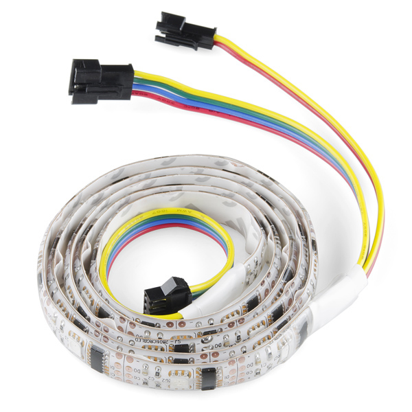
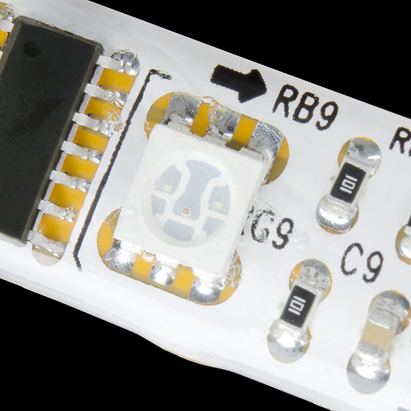
This RGB LED strip allows you to individually control all 32 RGB LEDs on a waterproof, self-adhesive strip. Each LED has its own WS2801 IC and current limiting resistors. Check the example code and datasheets below for more information on how to drive these strips.
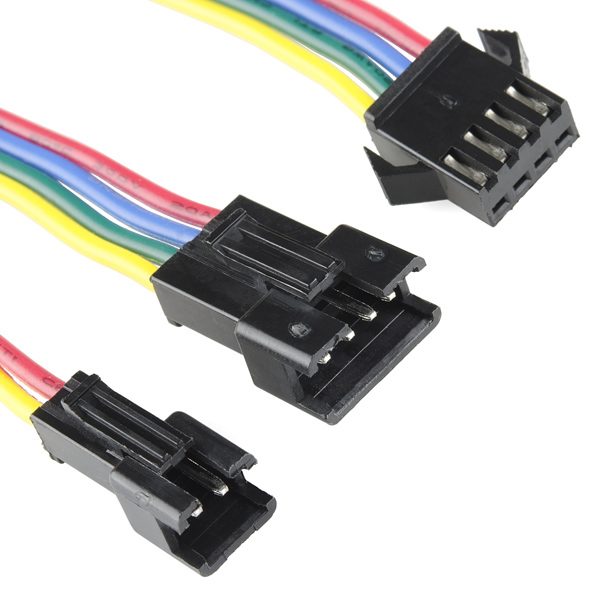
Each 1m section comes pre-terminated with 0.1" spaced 4-pin connectors as well as a 2-pin power connector. Please see example code for termination explanation.
Replaces:COM-10312
- Datasheet (FLB-W5050RGB-16-5-N14)
- Datasheet (WS2801)
- Example Code
RGB LED Strip - 32 LED/m Addressable - 1m Product Help and Resources
Core Skill: Programming
If a board needs code or communicates somehow, you're going to need to know how to program or interface with it. The programming skill is all about communication and code.
Skill Level: Noob - Programming will be limited to basic drag and drop interfaces like ModKit or Scratch. You won't be writing code, but you will still need to understand some basics of interfacing with hardware. If you?re just using a sensor, it's output is analog.
See all skill levels
Core Skill: Electrical Prototyping
If it requires power, you need to know how much, what all the pins do, and how to hook it up. You may need to reference datasheets, schematics, and know the ins and outs of electronics.
Skill Level: Competent - You will be required to reference a datasheet or schematic to know how to use a component. Your knowledge of a datasheet will only require basic features like power requirements, pinouts, or communications type. Also, you may need a power supply that?s greater than 12V or more than 1A worth of current.
See all skill levels
Comments
Looking for answers to technical questions?
We welcome your comments and suggestions below. However, if you are looking for solutions to technical questions please see our Technical Assistance page.
Customer Reviews
No reviews yet.
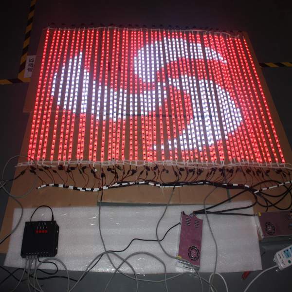
That's a very expensive display in the fourth image! There's 48 stripes, at 46.04$CAS each, that equals 2209.92$CAD.
I started messing around with this for a bike lighting project, and I think the code I wrote based on the example is a little nicer than the current example. (Uses hardware for comm, is more frugal with variable sizes.) If anybody's interested: https://github.com/SeanConnell/EElBikeLights/blob/eb46f7c860d2f68acfbb9eb9cc5071560d89f59b/lights.ino
Thanks to Nate for the example code! I owe you a beer.
I can't explain how excited I am that these have been replaced with new ones at half the price, twice the LEDs.
I'd like to drive this directly from a Raspberry Pi, but I'm concerned about timing issues. Is this possible? If so, can anyone recommend a low cost bridge between the two? Or point me to how I can go direct from Pi to strip? Thanks!
Given the datasheet am I correct in the current consumption ranging from 0.6 to 1.8 amp draw PER strip?
Just to verify: To make shorter strips I just cut along the line and modify the code for the proper LED count on the strip, yes?
FYI... These connectors are JST SM type connectors. JST 2-pin part number: SMP-02V JST 4-pin part number: SMP-04V
If all you need is to connect to a single strip, buy the pigtail that SparkFun sells here: https://www.sparkfun.com/products/11182 Otherwise, you can buy the pins and connector housings off of eBay or newark.com
Hi,The Red and Blue colours in my led strip are inverted :/,also my led strips does not match with picture shown above. I was working on ws2801 breakout and it works fine , when i set red -outs RED when i set blue-outs Blue but using theLED strip i noted that the colours RED & BlUE are inverted,Green is fine. Maybe some issues on how the LED was connected.
I need part numbers for the connectors. Can anyone provide?
how can I control a specific LED in this strip? For example, If i wanted LED #4 to only be lit and be green, how would I code that? Oh and I am using an arduino uno
I highly recommend checking out the example code (see link in product description). It's essentially handled like an array, where each array element is an LED in the strip. So strip_colors[3] would refer to the 4th LED.
Do you sell a 5 Meter version? Also, word of warning. I purchased the PRT-11182 pigtail and the wire colors did not match up. I used a small screwdriver to remove the pins/wires and arrange them to match the color coding on the attached connector. Glad I didn't let the magic smoke out...
How much does one of these strips weigh?
55 grams with connectors.
Spec timing violation. The datasheet timing diagram indicates that cessation of clock activity for >500us causes the shift register data to be latched into the driver registers. Each WS2801 has an internal low accuracy and stability clock, so the necessary interval is that of the slowest IC. My unit has sections which fail to latch for intervals < 770us, and no section works below 640us. All intervals verified by oscilloscope. Given the observed variation within one strip and expected additional variations between strips (different IC lots) and over temperature, users should budget around 1000us for the latch interval.
Does anyone have some other example codes that work with this strip i could play with? I am using an Arduino Uno. Thanks for any help.
Send me an email mrpetti@yahoo.com and I will send you some good stuff
I've tried to daisy-chain this model with the predecessor (https://www.sparkfun.com/products/10312). It doesn't seem to work, but as far as I can see the electrical connections are identical. Any ideas?
The power consumption may have been pushed too high for your supply once you added the extra units to the chain. Have you ensured that the power supply is strong enough to push all of the strips that you want to connect? Thanks Tim
The thing is, the first strip lights up and is addressable without any problems, but the second strip does not react at all. If power was an issue, I guess the first strip would not light up at all.
Actually I think the first line would work fine and then depending on the power capability you would see a degrading performance the farther you go down the chain. I have more data hiding in my old emails somewhere. If you want to discuss this more in depth I would be more than happy to start an email thread with you.
Just got this, seems to work great so far!
I agree with the previous poster that the wiring is confusing:
(3) These can draw a considerable amount of power when all the LEDs are on. If you daisy-chain many strands together, the first strand has to carry the power for all the strands beyond it, which can exceed the capacity of the internal wiring. To prevent this, additional power connectors are provided so that you still daisy chain a number of strands together (one data connection), but you can power each strand individually.
(5) The neat thing about this design is that you can daisy-chain as many strands together as you need (even the individual LEDs in a strand are daisy-chained in this way), hence the end connectors. And no, since the end connector is just outputs from the last LED and not bussed, you don't need to terminate them in any way.
Hi, I'm having some trouble getting this to work (I am pretty new to arduino and electronics btw). The wire colors on the item I received match those in the picture, but they do not match the example code (there is no black wire). It also seems like the red wire may be 5V instead of SDI as suggested by the example code, and I think that yellow must be GND? I can get the first LED to light up by just connecting the red wire to 5V and the yellow to GND (from the 4 pin connector on the side that also has a two pin connector), but I cannot get any other LEDs to light up at all. Any help would be much appreciated. Thanks!
Hey, I just got mine and had the same problem and played around with it for a bit.
Here is what I found out:
green = SDI / pin 2 blue = CKI / pin 3
the red and yellow wires are the power wires that are connected to each other. yellow power = gnd red power = 5v
Hope this helps!!
Watch the voltage, burned mine out.
What’s a safe limit for the voltage? e.g. would powering this with 4 AA batteries still be safe?
I wonder what the difference is between the WS2801 and the LPD8806 used in the Adafruit strip? I've used the LPD8806 controlled strip, and found it can be changed really quickly. In a persistence of vision test, I've put a one meter strip on the side of a car traveling about 60 mph, and can switch them such that I can display a readable character that is about 3 feet wide from a distance of about 100 feet away. I wonder if these can be switched as quickly as the LPD8806 controlled strip?
The data sheet is above. The max data rate is 25MHz. Divide that by the number of LEDs and you get down to 32KHz max refresh rate for all the LEDs in a strip. The PWM clock is 2500Hz so you might not be able to do a frame rate faster than that, but I'd be surprised if anyone found it "slow".
It requires a "latch" of 500us, so max is probably ~2kHz.
Looks like a great new product. When I've programmed other RGB LED strips (such as on the Mechatronic Tank on this page http://www.sparkfun.com/news/699), I offloaded the control of the strip to a separate microcontroller (such as an Arduino Nano or Arduino Pro Mini), because I was worried that the heavy load would interfere with the main operations of the robot (which runs on an Arduino Mega). Do you think I should do the same thing with this particular RGB LED strip, or do you think I could safely mix it into the main loop of a robot's main sketch without effecting the overall performance?
No worries for heavy load. Those strips of RGB LED will retain there colors automatically and forever until power is disconnected. You set them once.
The post_frame is call once. Everytime you want to change color, you change the array call "strip_colors[i]" and then call "post_frame()"
If you change the colors not frequencly, you will not overload your microcontroller. Even if you do it fast, you Arduino Mega will be able to handle it. BTW your "heavy load" really depends on how you code you main loop!!! Are you using a finite-state machine or simple loop and all your actions are in sequence? This will really affect everything.
That's awesome. This will be a huge improvement to what I was using before.
Regarding your question: My sketches generally use a simple loop with actions in a sequence. For example, it may be in autonomous navigation / object-avoidance loop or it may be in Remote Control loop and respond to user input, and so on. The previous LCD RGB strip product I used (which came from a different provider) involved a HL1606 chip, which didn't have PWM built in, so I had to code the PWM and keep it going, so I off loaded that work onto a auxiliary microcontroller. Because your strip is LAF (Launch and Forget), it should be much better to program and use.
Thanks for the new product.