- Home
- Product Categories
- Radiation
- SparkFun Geiger Counter

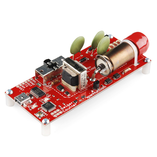
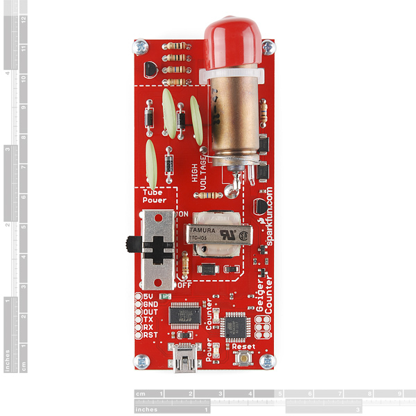
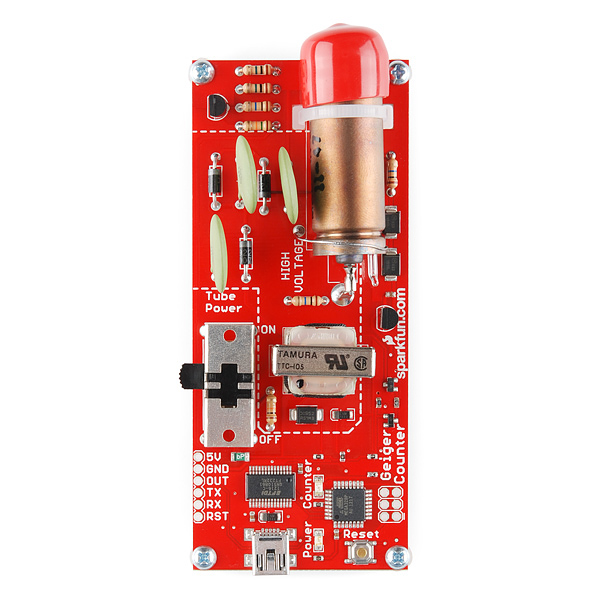
SparkFun Geiger Counter
You talked, we listened, and we've revised our Geiger Counter board to address some of the most pressing concerns. This version features an improved voltage regulation circuit for the Geiger tube which has a much cleaner output. We've also modified the signal capture portion of the board so that it reads active high, allowing for more dependable counts that are less susceptible to fouling due to line capacitance. The new signal capture circuit also pushes the CPM limit to 100Hz!
This USB powered SparkFun Geiger Counter is equipped with an ATMega328 that can be programmed in circuit using one of the programmers below. Simply plug the unit into USB (make sure you have FTDI drivers installed), open a terminal program to the correct COM port at 9600bps, and you will see random bits being generated from the random background radiation. Each bit generated (an ASCII byte 0 or 1) represents an actual event in the tube in real-time, so the output can be used to deduce CPM or what ever units you need. While you're at it, why not check out the random number generating Geiger counter tutorial?
Note: While the Geiger counter is powered and the switch is in the ON position, the board contains exposed high voltage components. In order to turn the unit off, you must flip the tube power switch to OFF while the USB cable is plugged in or while the board is still connected to your power supply. The reason being; when you move the switch into the OFF position, the high voltage lines are bled out through a resistor connected to ground, more information on this is in the tutorial.
A project box or enclosure is suggested. Do not touch the end window of the Geiger tube and do not to touch any conductive region inside the area marked HIGH VOLTAGE when the Geiger tube is powered ON. An enclosure is not absolutely necessary, but if you choose not use an enclosure, remember to be extra careful with the end window and high voltage regions.
The Geiger tube comes with a red boot to protect the end window during production, handling, and shipping. The boot should be removed if you need to detect alpha particles. However, you should still see activity from gamma and beta particles even with the boot on.
This product is controlled for export by the United States. Sending it to other countries may still be possible, but will require additional information prior to shipment.
Note: This product is for educational purposes and should not be directly relied upon for determinations regarding one's health or safety.
Features:
- 5V Logic
- Total Current 30mA
- LND712 Geiger Tube @ 560V
- ATMega328 Microcontroller
- FTDI USB Interface
- On Board Power and Status LEDs
- TTL (Active High) Output Pin from Tube
- Arduino bootloader included. Use board type “Arduino Pro or Pro Mini, ATmega328 (3.3V, 8 MHZ)
- 4.15"x1.75"x1" (w/o standoffs)
SparkFun Geiger Counter Product Help and Resources
Core Skill: DIY
Whether it's for assembling a kit, hacking an enclosure, or creating your own parts; the DIY skill is all about knowing how to use tools and the techniques associated with them.
Skill Level: Noob - Basic assembly is required. You may need to provide your own basic tools like a screwdriver, hammer or scissors. Power tools or custom parts are not required. Instructions will be included and easy to follow. Sewing may be required, but only with included patterns.
See all skill levels
Core Skill: Programming
If a board needs code or communicates somehow, you're going to need to know how to program or interface with it. The programming skill is all about communication and code.
Skill Level: Rookie - You will need a better fundamental understand of what code is, and how it works. You will be using beginner-level software and development tools like Arduino. You will be dealing directly with code, but numerous examples and libraries are available. Sensors or shields will communicate with serial or TTL.
See all skill levels
Core Skill: Electrical Prototyping
If it requires power, you need to know how much, what all the pins do, and how to hook it up. You may need to reference datasheets, schematics, and know the ins and outs of electronics.
Skill Level: Noob - You don't need to reference a datasheet, but you will need to know basic power requirements.
See all skill levels
Comments
Looking for answers to technical questions?
We welcome your comments and suggestions below. However, if you are looking for solutions to technical questions please see our Technical Assistance page.
Customer Reviews
3 out of 5
Based on 1 ratings:
2 of 3 found this helpful:
Strange
With all that hardware on board, hard to understand why we need another arduino to make something useful out of this. Any event is visible on the green LED, but that output is not pinned out - it would be nice to be able to connect piezo to hear raw counts (like in every other geiger I have ever seen!!) - or simply to generate a rolling average. What is the reasoning behind the serial output being a 0 or a 1 randomly each time the GM tube fires? And why isn't there code for this?
I'm not the first to ask - what is the breakdown voltage of the 2x zener diodes? I am trying to decipher the workings of the voltage multiplier and the hole thing rests on the effective breakdown of these two zeners in series. A little help from someone?
I don't get it - $3 worth of parts and a $93.95 Geiger tube??? You can buy Geiger tubes for $6 to $16 on an auction site and build your own HV supply from a handful of parts. Why match choose such an expensive Geiger tube for an experimenter's project? And they don't even provide a radiation source sample for you to check the thing out! By the way, you can buy smoke detectors that have an Americium radiation pellet in them for about $5. Rip it apart and the Americium pellet is a great radiation source for testing and calibration.
I made a VERY simple case for this if you want to print one :) https://www.thingiverse.com/thing:2370044
I'm having some issues with mine. When I turn it on, i can see the 1's and 0's and the green LED flashes. Then after a good 30 seconds it stops working. No LED flashes. I then try to turn the tube on and off, a bunch of time, it doesn't work.
Any ideas how to get it working consistently?
GRRRRR. DO NOT try to remove the effing red boot and put it back on to switch between measuring/not measuring for alpha radiation.
The boot refuses to go back on because the tube is zip tied to the board, and trying to get it there (being as absolutely cautious as possible) will likely result in breaking the Geiger counter, even though the red boot just fit on it 60 seconds ago. Also take careful note of the little extra-fragile glass tube at the back of the Geiger tube.
Recommend a design change to account for changes between alpha radiation measurements.
Why does the binary output resolve to a 0 or a 1 for an equivalent event in the tube?
What is the difference between a 1 or 0 in the data stream, if any?
In other words, should the output be interpreted as 1 = 0 = radiation event?
Hi there! Is there any code for trying using this sensor with an Arduino? Because I'm thinking on a project for datalogging the radiation with a GPS... Well, if someone has a code that can show the uS/h or something similar, this would really help me!!!
Using dose units is pretty meaningless because they'll be wildly inaccurate without proper calibration. Radiation detection instruments outside of some specialty ones are typically calibrated to Cs-137. You have a rig that puts the instrument at a precise distance of known calibrated activity and energy and use that to calibrate the unit which is the conversion factor for CPM/CPS to dose rate, which is only good for that individual instrument. There are more factors to consider like using Hp(10) or H*(10) dose calculations. H*(10) are normally search instruments, and dosimeters use Hp(10) which is the dose calculated at 10mm penetration in a flesh analog. Also exposure rate varies dramatically with distance dosimeters have to be worn on the body. The chest preferred for whole body exposure. It gets more complicated with weighting factors(Wr) for type, body parts, and organs to calculate the final dose.
Once you have it calculated it will only be accurate for Cs-137 which, and I'll use only gamma energies for this explanation, emits gamma photons at 663KeV. Another, say Co-60 emits gamma photons at 1.173MeV and 1.332MeV. So in layman's terms a single count from a Cs-137 source will have less energy than a single count from a Co-60 source. I'm going to use uSv/h but to be totally correct it should be uGy/h for absorbed dose, so I'm using a weighting factor of 1 for gamma rays to get the uSv value for what a whole body effective dose rate would be theoretically. At 37kBq @ 1cm with a 100% theoretical exposure the H*(10) dose rate from Cs-137 would be 28.3 uSv/h, Co-60 would be 113.7 uSv/h, and very common Potassium-40 (K-40) would be 6.8 uSv/h. That's why using dose measurements with a geiger counter, unless you have a known source, is fairly pointless. With unknown sources such as background the standard to use is CPM or CPS for good reason. There are ways to energy compensate a GM tube so it can be used in dosimetry which essentially puts a material around the tube to level out it's energy response as much as possible. Dose will still be inaccurate for anything it's not calibrated for, but less so than without it. The trade off is it loses some of it's detection sensitivity. That doesn't matter for a dosimeter, but it does for a general purpose instrument.
Also be aware that count comparisons between different instruments are not always accurate unless they use the exact same GM tube, and even then the detection circuitry can affect things. Every model of geiger tube will have different count rates. Larger tubes tend to have more than smaller ones. Different tubes also have different detection efficiencies so even with very similar sizes if there's a source energy that ones tube is not very good at detecting there will be difference in count rates.
You can find an example sketch for using this with an Arduino Ethernet shield here. That sketch is going to be a little overkill for what you're talking about doing, but the function you want to focus in on is this:
void geiger_CPM() {
while (mySerial.available() > 0) { int inChar = mySerial.read(); if (inChar == '0' || inChar == '1') { count++; } }
Hi there! I just wanna use this with the Arduino IDE. Meaning I would like to change the code (for example to output serial or analog, or to have CPM or CPS) without needing to change the bootloader.
Is there a way? i am tired of hacking it whenever I want to change small things like that. :(
Thanks for asking! The Arduino bootloader is already on the board so you can upload your own firmware if you want to. Just use board type “Arduino Pro or Pro Mini, ATmega328 (3.3V, 8 MHZ)" in the IDE.
One warning though. We don't have an .INO sketch of the original firmware so if you reprogram the board, you can't go back to the original firmware without using a hardware programmer.
Hi I have one these and the original tube has a pierced tube. I would like to change it with another tube that obviously works @ a different voltage. Is there any fast way to change the output voltage?
Anybody ever going to fix the sparkfun CPM feed?
Not that it's important, but it's just a little sad when you go there and it still doesn't work.
They had 2 this morning, but now there out. I was waiting for approval from my son's science teacher before I bought it, which he just got. He wants to compare radiation levels near his school (by the World Trade Center) with a rural area. I hope they are in stock soon.
*Ping*: 4 just came in stock
I've created a case for this if anyone wants.
http://www.thingiverse.com/thing:260923
Hi can you please explain to Arduino newbie how to update the firmware? I have counter hokked up and working fine - shows some 1 and 0 coming from my serial (USB) port. Have Windows 7 + Arduino 1.0.5 IDE - and IDE sees the board. There is a C code for new firmware V13 but I have no idea how to get compile it using Arduino IDE? Sorry just lack of experience in this area yet...
Can anyone let me know what this board weighs? Thanks!!
Would also like to know. It would be nice if products had weight listed on the description.
Curiosity I may have missed it but in the video ther is an analog meter attached to the Gieger counter demonstration. What is it's specs?
Customer project with the Geiger Counter, microView and a 3D printed enclosure => http://www.thingiverse.com/thing:854368.
How can I re-flash the device from linux? I would like to put the v13 firmware in it. I tried e.g.: avrdude -c stk500v2 -p m328p -P /dev/ttyUSB0 -U flash:w:geiger_main-v13.hex but this gives timeouts.
Ok I reverse engineered the firmware (that is: rewrote it). http://vanheusden.com/Arduino/sparkfun_geigercounter_fw_reveng.tgz That tar file includes an "arduino-mk" compatible makefile but if you load it into the arduino ide and choose the "arduino pro or pro mini (3,3V, 8MHz) w/ atmega328 then it'll work as well.
works well
I want to buy this product to measure Radon (that emits radiation Alpha). Someone has already implemented something like this?
We are having some trouble getting it going. We thought the "Friday" video on Sprakfun used analog port, but some tuts we've found use serial port (Tx on Geiger, Rx on Ardunio Uno). Like http://www.instructables.com/id/Arduino-Geiger-Counter/ wherein he uses a serial 16x2 LCD to see data. We want to see it on our serial monitor AND log it to SD card. We get something like 214K for a value, and no, this place doesn't glow in the dark. Suggestions? Has anyone logged this to SD card (with other sensors?)
BTW - our Geiger weighs about 50 gms. We are having some trouble getting it going. We thought the "Friday" video used analog port, but some tuts we've found use serial port (Tx on Geiger, Rx on Ardunio Uno). Like http://www.instructables.com/id/Arduino-Geiger-Counter/ wherein he uses a serial 16x2 LCD to see data. We want to see it on our serial monitor AND log it to SD card. We get something like 214K for a value, and no, this place doesn't glow in the dark. Suggestions? HAs anyone logged this to SD card (with other sensors?)
Hi there. What is the value of the Zener diodes U$6 and U$7 in the schematic? Thanks.
Extremely expensive
How can I see the firmware I have inside the device I just received ?
I want to make a smaller board, do you think it's possible ? or do I have size constrains and mandatory space between coponents ? Thanks
any box/enclosure recommended ....?
If you want to connect to the Radiation Network all you need is a TTL-232R-5V cable and connect the red wire to +5, the black wire to GND and the yellow wire to the pin 28 side of R13 (i.e. the green LED output).
Just got one of these. Mine 'ticks' from somewhere on the board but it seems to count events fine and no false events from the ticking. Thinking the ticking might be from the switch, I unsoldered it, but something is still ticking.
Some suggestions for the next version: - break out the remaining pins - ship with Arduino bootloader; those who don't want it can easily remove it and those lacking avr-gcc skills will have an easier time modding it.
Can anyone post a higher res picture of the board?
I'm trying to integrate this circuit into another and the schematic is horrible (full of vague or incorrect component descriptions). Is the v30 schematic listed the same as the board that is pictured?
please anserve
Geiger tube movies build inside site, please put Video of the work out Geiger counter with LCD display Model 11345 inside site, please put
Hi, I want to make a Geiger Counter SEN-1134, which be have a LCD as shown in Figure below was the Count and specify give own time. price How much? I send you the photo on Facebook
Hi, I'm integrating this counter into a smaller board for a project. Does anybody know SMD high voltage capacitors that can replace the original ones? I tried these ones: http://www.vishay.com/docs/28515/hv1kv2kv.pdf but somehow they make the high voltage peak present in the transformer 4th terminal disappear, and hence, the output voltage drops significantly. Any suggestions? Thanks!
The live geiger counter feed seems to have flatlined.
Maybe we missed a highly localized apocalyptic event on May 23rd.
It was a highly localized apocalyptic event! We actually lost our engineer Aaron to a bigger, better job in California, and he apparently took the Geiger counter with him. I'm working on getting another one set up here though, so hopefully the feed will be up again soon!
There is a working example here: https://xively.com/feeds/126898/
how much power does the device use? (in mA)
and can it be build in a closed box or does it need ventilation?
Adafruit sells a Geiger counter kit that runs on AA batteries, but you have to solder it (fun! If you can solder) for only $100: here
I connect that board to usb and read from /dev/ttyUSB0. When I read byte by byte I've got '\n', '\space' 11 times, '\n' and that's all.
Green 'Counter' led blinks from time to time but no more bytes read in tttyUSB0. Is that correct?
Problem solved by stty -F ttyUSB0 raw
Any suggestions as to the best windows based software solution for the SEN-11345?
It depends on what you mean by 'software solution'. This outputs basic serial data, so you could use any program that reads serial data such as CoolTerm, TeraTerm, Hyperterminal, etc. You could also use something like a python script to port this data into Xcel or something like that.
Hi
I have the old version i think code 7-18-11. its been working fine for about 1 year logging away but today its just went out of control started reading 80 CPM (I hope out of control anyway). I reset it did the standard turn it off and on and now its reading nothing. Is this a common symptom when it fails to give such large CPM counts ?
Thanks,
Howdy kiddos, I'm looking into making something that can ballpark the amount of detected radiation. I've done a bit of reading, and at the very end (of course), I discovered this great Q&A. I wanted to share this, and then see if anyone else has had luck with calculating the efficiency factor and geometries for their detectors? http://hps.org/publicinformation/ate/q1509.html
(This Q&A discusses converting CPM into DPS, and then to Curies. Cool!)
How to measure radiation with it?
How do you program to V13?
What voltage do the TX & RX pins at the jumper connected directly to the ATMega168 operate at? For my application I will NOT be using the FTDI-USB port, I just want the raw UART data as this will be easier to interface with my micro. The micro I am using uses 3.3V I/Os, will I need a level converter? In the past I have gotten away with a voltage divider. Thanks for the help!!
-Nathan
Just wondering if that ATMega328 is rad-hard? :-)
Probably not. Though I'd say if you're using this is an area where a rad-hard uC is necessary, you have bigger concerns :)
Looks like you may have solved my problem with a bigger switch... I have a previous version of this board that developed a problem where the power switch was arcing internally, causing a failure to register radiation events. The "snap" sound of the arc was audible, and if you inspected the power switch at the correct angle, you could even see the corresponding flash of light. I fixed it by cutting and desoldering both leads on the "OFF" side of the SPDT switch. Evidently it was arcing from the center pole to the OFF side. Just FYI, in case anyone else has this problem with the older version of the board (the one with a tiny surface mount switch). Looking at this newer design, I doubt it will continue to be a problem and I'm guessing this is why SFE elected for a larger switch in this updated model. Don't throw away your old board, though! It's a quick fix. :-) Cheers! ~P
That sounds like one of the first revisions and that is exactly what we saw on occasion.
We have rev'd a lot since then, including the switch, the HV circuit is much better now as well.
I just received the newest version (with the large switch) and can hear what sounds like a small arc every 750ms or so. However, I have been unable to see any visible arcing and the unit appears to be working correctly (10-15 CPM using custom firmware). I don't have an HV probe for my scope, else would use that to check it. Whatever it is, it ticks like a clock.
Mine has the same 750 ms tick as well, however mine registers a count with each faint tick. Adding capacitance to (pinching) C4 seems to decrease the frequency. Adding a bypass resistance (light finger touch) across R14 seems to decrease the sensitivity enough to eliminate the 750ms periodic trigger (despite the audible noise remaining). Thoughts? Am I seeing a non radiation induced (ie over voltage) dielectric breakdown in the tube? Is that tick the capacitors' dielectrics talking or a breakdown occurring? I guess I will add an adjustable R14 bypass and adjust the sensitivity just below it picking up the tick (not my favorite fix though).
Are you saying that every 750ms you get a registered count (i.e. LED lights)? That isn't normal. However, there is some noise from the oscillator on the tube, but the Vmax through the TTL circuit is no more than 1V, so it shouldn't register an event. During my testing, I couldn't correlate the periodic noise to an event and the geiger counter I have connected to the feed, seems to work just fine.
Yes, that is correct, I get a periodic blink (and a serially transmitted 0 or 1) every 750ms (and about 20-30 additional, but non-periodic events a minute). I do get counts from radioactive sources (ye olde school anti static brush) but there is presumably the approximately 80 cpm offset. I'll scope in as far as I can and get back to you, but I don't have a 50x or 100x probe.
Yea, you probably want to contact techsupport@sparkfun.com and they can get you a replacement. We haven't seen this behavior, so we want to take a look.
Either in a cardboard box or out of it, my geiger counter reads about 10-20 cpm. Does this make sense? Is there a way to verify proper functioning?
My geiger counter reads about 15 CPM per minute. How is CPM converted to other units like uR/hr?
were you able to figure it out?Also would like to know how to convert to uCi/liter in case measuring radon levels...thanks
Looks like iphone is 3.3V. I guess easier to add separate Arduino and power supply. I'm assuming it is hard to add LCD directly to 11345.
hello, did you have a chance to hook it up with your iphone? Thank you
The TX line is broken out, so it would probably be very easy to attach a serial-enabled LCD.
I just bought one and want to make it portable. It would need a power supply and display. It could be attached to an Arduino with an LED display and a battery pack. It might be able to work with a smartphone. It does not appear to draw much current. Anyone try to make it portable?
I just ordered this yesterday. Will I get the new revision?
I bought the previous version and commented about the HV regulation and the Geiger tube output signal processing . I would like to retrofit my older version to this one, any idea when the revised schematic will be posted?
Also, I did not checked the posted firmware, is it the current one?
I know you guys are busy... Merry Christmas!!
If anyone interested, I recently did a few tutorials on how to build a geiger counter using the LND712: http://www.youtube.com/watch?v=m8GIeZAxLYs
and don't forget your Uranium Ore! http://unitednuclear.com/index.php?main_page=index&cPath=2_4
While these are out of stock and have obsolete documentation, a good alternative is the Mighty Ohm Geiger counter kit. It doesn't have the alpha sensor capability, but it's a high quality and easy to build kit, has clicker sound, and comes with a "case".
Can you show me the obsolete documentation? As far as I can tell, everything is up to date.
Unless I'm missing something, the schematic here is still for the old version.
Please update the schematic file.
Is there a high demand for these, or are they just difficult to build? (or both) (or, I guess a low demand would explain it too...) I ask this because of the relatively low stocks of these.
a little of both. they're not THAT easy to build since they have both SMD and PTH. they basically take two building cycles since we do the pick-and-place first, and then everything else. Plus, the tubes are fragile so they take a bit of extra time with cleaning and such. it's much easier to build a panel of 20 pro-minis than a couple of these...
They are easy to build. There was a spike in demand for Geiger tubes after Fukushima. Seems like the only consistent source of Geiger tubes is from Russia.
712! Can this be sent to Canada?
I've received mine after 3 week. All good.
With customs at the Canadian border I wouldn't guarantee anything every. But if you return the form Sparkfun sends you you have as much chance as a solar panel or assortment of capacitors. I received mine with no problems or delays.