- Home
- Product Categories
- 7-Segment
- SparkFun 7-Segment Serial Display - Yellow

SparkFun 7-Segment Serial Display - Yellow
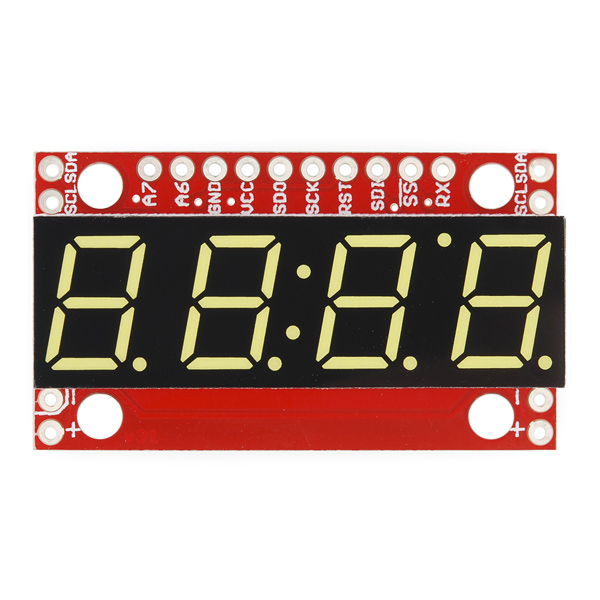
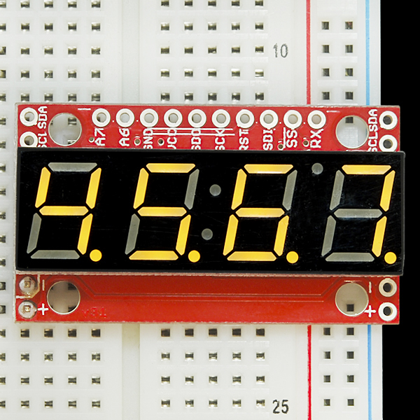
4-digit 7-segment displays are really neat little devices, it's a shame that they can be so cumbersome to control. Well we've solved that problem by making them a little bit "smarter." The SparkFun 7-Segment Serial Display combines a classic 4-digit 7-segment display and an ATMega328 microcontroller allowing you to control every segment individually using only a few serial lines.
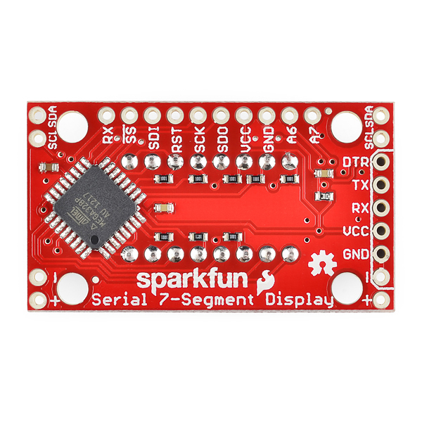
The Serial 7-Segment Display can be controlled in one of three ways: Serial TTL communication, SPI serial communication or I2C serial. You can even program it for stand-alone operation since the ATMega328 comes pre-loaded with the Arduino bootloader! There is also an FTDI header on board and we've provided a hardware profile for the Arduino IDE to make it even easier to program.
We've made some layout changes to this design as well which will make it easier to incorporate these into your project. We've moved the power and I2C pins to the sides of the board such that you can chain them together in order to display longer strings of digits. We've also added mounting holes to the boards so you can mount them on standoffs (no more hot glue!)
Replaces:COM-09764
- 4 digit yellow alpha-numeric display with TTL, SPI or I2C Serial Interface
- Display numbers, most letters, and a few special characters
- Individual control of decimal points, apostrophe, and colon
- Selectable baud rate
- Selectable brightness
- Baud rate and brightness values retained in non-volatile memory
- Individual segment control for each digit
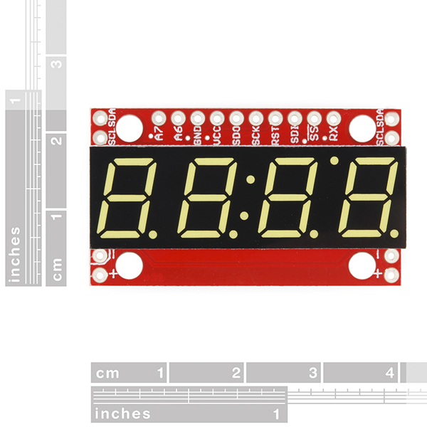
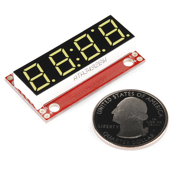
- 41mm x 23mm (1.6in x 0.9in)
SparkFun 7-Segment Serial Display - Yellow Product Help and Resources
Using the Serial 7-Segment Display
August 13, 2013
How to quickly and easily set up the Serial 7-Segment Display and the Serial 7-Segment Display Shield.
Dungeons and Dragons Dice Gauntlet
August 13, 2013
A playful, geeky tutorial for a leather bracer that uses a LilyPad Arduino, LilyPad accelerometer, and seven segment display to roll virtual 4, 6, 8, 10, 12, 20, and 100 side dice for gaming.
Core Skill: Soldering
This skill defines how difficult the soldering is on a particular product. It might be a couple simple solder joints, or require special reflow tools.
Skill Level: Noob - Some basic soldering is required, but it is limited to a just a few pins, basic through-hole soldering, and couple (if any) polarized components. A basic soldering iron is all you should need.
See all skill levels
Core Skill: Programming
If a board needs code or communicates somehow, you're going to need to know how to program or interface with it. The programming skill is all about communication and code.
Skill Level: Rookie - You will need a better fundamental understand of what code is, and how it works. You will be using beginner-level software and development tools like Arduino. You will be dealing directly with code, but numerous examples and libraries are available. Sensors or shields will communicate with serial or TTL.
See all skill levels
Core Skill: Electrical Prototyping
If it requires power, you need to know how much, what all the pins do, and how to hook it up. You may need to reference datasheets, schematics, and know the ins and outs of electronics.
Skill Level: Noob - You don't need to reference a datasheet, but you will need to know basic power requirements.
See all skill levels
Comments
Looking for answers to technical questions?
We welcome your comments and suggestions below. However, if you are looking for solutions to technical questions please see our Technical Assistance page.
Customer Reviews
4.5 out of 5
Based on 2 ratings:
1 of 1 found this helpful:
Easy to get up and running with an Arduino
The example code and circuits are pretty complete. Not much to say, it just works.
not very bright
The red one is nice and bright, but side-by-side, the yellow one is quite dim on 5 volts. Very easy to use with "debug" in PIC Basic Pro. debug "v", N dig 3, N dig 2, N dig 1, N dig 0
The only stupid questions are those not asked.. So, how do I use the onboard ATMEGA to control the 7S and read data from an analogue pin? (for ex the RHT03 temp and hum sensor) Bonus points if I can use I2C as well for daisy chaining these together..
I assume that all segments will bright equal compared to earlier version of this display? It did just sucks. But why the heck this new revision comes with different pinout/orientation? Not compatible to my PCB at all :(
Please provide this display pack with white and 1" 7-seg display.
Looks like the old version is still available. +1 on the 1" suggestion.
+1 again on the 1" suggestion
Hello friends. I have managed to destroy the 328P on my Sparkfun board applying 24V to it by using ACS712 Ampere meter from china. Since that time, display was dead. I resoldered the Atmega328P to the board and tried to burn bootloader via arduino. I downloaded Serial7SegmentDisplay-master, placed it into my sketch folder, also modified the "boards.txt" file to have the display listed. Then i tried to upload bootloader via Atmelstudio and AVRisp mkII (i have used the file mentioned in "boards.txt"), programming and verifiing went fine, but display still does not respond to i2c messages i have used until i destroyed it. Then i made my Uno ISP programmer and i have choosen it in programmers and tried to burn bootloader. Here i got this message: avrdude: Yikes! Invalid device signature. Double check connections and try again, or use -F to override this check. And now i dont know what next :)))) MISO and MOSI are correct.
I am using Arduino 1.0.5 on Windows 7 x64 The 328P is brand new, and i have used SMD rework station to unsolder the broken one and solder this new one.
Thank You very much. Dusan
I'm guessing you fried the 328P... It's max voltage is 5.5, so you'll most likely need a new 328P but even then other on board components may of also been fried
Hello,
i have replaced the 328P, so now i am using "blank" 328P which i wanna "fill" with firmware. Via Atmel Studio i uploaded optiboot bootloader "optiboot_atmega328,hex".
I also have USB2SERIAL adapter from Arduino "http://arduino.cc/en/Main/USBSerial" and this way i am trying to upload firmware sketch from Arduino.
The header on the end does not seem usable as you can't connect anything to it - the LED is covering the holes. How was it intended to be used?
Solder it from the bottom as i did :) No problem
Am I correct in assuming that I could attach other I2C devices to this and have the internal atmega328p act like a I2C Master?
Hi,
I'm trying to build a COM-11443 on a breadboard. I am using a 328P. I downloaded both versions of the software from GIThub. (Master and v3.1_live.) I can't get either one to work properly. The 3.1 version displaies 3 mangeled "5's" on the right most LEDS. (The bottom segment is missing.
The master version displaies all digits, but nothing resembling what I write to the serial port. The diaplay also has bad flicker.
I verified that the connections from the MPU and display are correct according to the software definitions. I also changed to the S7S in the define without luck.
Which version of the software works?
Is there anything else that would be giving me trouble?
Thanks in advance,
len
Keep that define as S7S, that should work with this schematic. Is the ATmega running at 8MHz? The CKDIV8 bit in the low fuse byte should be unprogrammed (set to 1); fuses set to L:0xE2, H:0xDE.
If that's all correct, double/triple check that all of the Arduino pins match up to the segments and digits they're defined as (see around this area of System_Functions.ino (I just added a new commit to make those comments more clear).
I pulled the chip and verified the display wiring, all the segments lighted as expected. I'll burn a new chip and see if I can make it work.
More to come..
I'll take a look again at it tomorrow. I do have the flag bits set as above, same as on the boards.txt. Maybe I'll try a new chip...
What's up with the 3.1 branch? Is that a new branch with the serial lib merged in?
Len
Just got this display working with a chipKIT UNO board using I2C. Connected the +5v, GND, SCL, & SDA lines. No pull-up resistors were required(the internal pull-ups are enabled on the backpack).
The chipKIT is a 3.3v device(with 5v also available on-board), and I have seen no problems with the backpack having any trouble reading this logic level. i.e. it doesn't look like a level converter will be necessary.
I wrote a driver based on the Github Repo examples referenced above. I have written drivers for SPI and Serial also, but have not tested these at this time.
Think out how you intend to mount/test this board BEFORE you solder in the pin headers. I didn't. DUH! I populated the 10 pins on the long side and 4 pins on a short side and now the board won't plug into my prototyping board. So, I'm connecting with jumpers.
This release of the display seems nice and bright.
James, KE4MIQ
Update1: I now have the SPI and Serial drivers working. Still no problem with the chipKIT 3.3v levels.
Update2: Code posted on http://www.chipkit.org/forum/ Topic: "Sparkfun 7-Segment Serial Display - COM-11443"
James,
Mind sharing your I2C code? I'm also using a PIC32 and have not have any luck getting the display to respond. I'm using a UBW32 board and am getting great signals to the display, but no response and I'm getting NACK's for every byte sent. I'm wondering what SCL rate you're using. I've tried a range from 3 kHz up to 100 kHz with the same lack of response. Like you I'm using no pull up resistors and there is nothing else on I2C2 except the display. I set the TRIS register correctly since my logic analyzer is showing good signals to the device. Thanks in advance! Regards, Ed Long WA4SWJ
Is there anything special about the new version of these displays? I'm having trouble getting it to work with i2c which I need. I'm using a Picaxe micro. I only need +, -, SCL and SDA right? In Picaxe BASIC I use something like: hi2csetup i2cmaster, DISPLAY_I2C_SLAVE_ADDRESS, i2cslow, i2cbyte ; address is 0x71 hi2cout 0, (0x76) ; reset display hi2cout 0, ("x", 0, "x", 0) ; initial value but for some reason this isn't working. Anybody else using this device in combi with a Picaxe and i2c? What about the slow/fast and byte/word i2c protocol settings for this device? The Picaxe itself is working fine, happily blinking a LED on a different port. The code for changing the display has no effect though.
I'm using a 4.8 V wall adapter. That shouldn't be a problem right? The online example however mentions: "Also make sure to power the display at 5V!" https://github.com/sparkfun/Serial7SegmentDisplay/wiki/Arduino%20Examples
Wires are: SDA to SDA, SCL to SCL and two 4k7 resistors as described in Picaxe manual.
I've bought two displays and both of them aren't working (all LEDs stay off) so it would be strange if both i2c headers are soldered incorrectly. Power is also ok, so those headers are soldered ok; when I touch the serial Rx pad with my finger the display turns to all zeros just fine.
What am I missing?
[SOLVED] I fell into the "i2c addressing" trap... D'oh! The Sparkfun datasheet mentions 0x71 as the slave address, but this is a 7-bit address. The PICAXE command requires an 8-bit number so you have to shift the address left 1 bit. That solved it. So the 0x71 becomes 0xE2 (confusing in my opinion). And yeah...it's in the command info...which is clear...when you understand the problem... :-) The PICAXE BASIC command should have used the i2c addresses directly, in my opinion, like the Arduino Wire library. Why the need to bother the high-level BASIC command with low-level i2c protocol r/w bits. I did notice that I now have to use a 0x76 reset command when setting the 4 digits in a while-loop: main_loop: pause 500 high LED_PIN hi2cout 0, (0x76, "x", "0", "x", "8") pause 500 low LED_PIN hi2cout 0, (0x76, "x", "0", "x", "0") goto main_loop: Without the 0x76 the display doesn't seem to use the correct cursor position and the numbers started to shift. Not sure why that is but I'll probably get that eureka next week :-)
[SOLVED] Quick eureka. Although I don't really understand it. When removing the address (0) from the hi2cout command, it seems to work. As if it's interpreted as a data byte (?). hi2cout ("x", "0", "x", "8") ; this now works Hope this will help other PICAXE/i2c/7-segement users.
Have been struggling with this unit and a PICAXE 08M2 chip for a while now... pretty frustrated. Have 4.7K pull-ups on SCL and SDA lines, Vcc= +5V. Here is my code to test I2C interface:
; PICAXE 08M2 / Sparkfun COM-11443 4 digit 7 segment display ; I2C Test
symbol Digit0 = b8 symbol Digit1 = b9
symbol slvAddr = 0xE2
MAIN:
NXT: high 4 pause 250 hi2cout (Digit0,Digit1,"0","X") low 4 pause 250 hi2cout (Digit1,Digit0,"X","0") GOTO NXT
END
The LED blinks nicely off pin 4, but the serial display remains dark and mysterious. Anyone have more of a clue than me?
I managed to set it so i2cfast but slow also worked. Software look alright... - did you perhaps reprogram the i2c address? - did you power the display board? ;-) - I managed to get some 0000 displayed when touching the serial Rx pad, waking up the display and showing that it's ok - double/triple check the connections :-) Crossed SCL/SDA?
Thanks for reply, Yopster!
Might have reprogrammed the i2c address...I will check on that (at work right now...shh!). I have checked connections more than times than i can count, LOL. I am using the (+/-/SDA/SCL)connections on one end of the board. I used a meter to make sure board was powered up and I also can get 0000 showing by touching Rx pad. I used an analog oscilloscope to monitor SDA/SCL above and below. I can actually see the SDA blurting out the address 01110001 over and over, but no other data, it doesn't seem to be in proper phase with the clock. Does the Chip need a proper ACK before it will send other data? I would think so. OSC is very old and surely out of calibration. I also have a Nano digital osc but it only reads one channel, so phase comparison is not possible.
I will look into the I2C address and see what I need to do to reset it.
Update- Tried resetting the I2C address..still no love. I tried a range of setfreq settings in combinations with i2cslow/i2cfast (sent my serial 2x16 LCD off to wild places!). I am beginning to think I got either a bad part, or I need to get an I2C book and learn the protocol so that I could teach it.
Signed, "ready to throw in the towel".
I'm getting a decent amount of flickering in my display when just keeping a temperature readout on the screen (updates infrequently). I'm driving the thing off an arduino uno, and the uno is plugged into a 9v wall wart.
Is there a capacitor I could add somewhere or something I could do to reduce the flickering? It's not real bad but it would be nice to reduce.
Repost from blue display:
Ok we (I am working together with Member #4643) have been working on this one for a few days, had a lot of trouble. We mostly worked with the ‘ Serial_7_Segment_Display_Firmware.ino ’ in which the pinlocations seemed to be wrong, at least they do not correspond with the parallel connection. We tried everything, also in the SevSeg.h files etc. but without any clear result. Luckily we just fixed the ‘problem’! It seems that everything is correct but one little thing, finally we found out that only this should be changed in that firmware Arduino code: On line 38: Original:
define DISPLAY_TYPE OPENSEGMENT
Changed into:
define DISPLAY_TYPE S7S
The other thing was the pin location, the provided schematic is incorrect!
So for further use: Please fix this part in the firmware code and change the Schematic sheet!!
Why is there no Crystal or oscillator on this board? Doesn't the 328 need one? There is also no place I see that specifies what Vcc should be. I assume 3.3v.
The 328's also got an internal 8MHz RC oscillator, which doesn't require any external components to operate. Selected in the fuse bits. Good thing it's there too, because I don't think we'd have enough output pins to control the LED otherwise.
This page of the datasheet's got a bit more info on the input voltage range. They can mostly be derived from the 328's datasheet. It definitely works in the 3.3V-5V range, and a bit outside that.
We have wired up this nice unit with an FTDI Basic 3.3V, installed the hardware profile for the Arduino IDE, but can't make the display work. We wrote a sketch with Serial.begin(9600) and Serial.write('2') but nothing appears on the display. The Arduino Examples section on the Github is empty, and so is the Customizing the display section.... help!
Good job Sparkfun! Mounting holes... it seems to be catching on. I am grateful! Keep it up. Hopefully the pro micro is next in line for holes of it's own.
Nice, if you want to use it as an ardruino, it it has breakouts for two analog inputs! That pretty much resolves all my complaints.