- Home
- Product Categories
- Robotics Kits
- Spider Controller

Spider Controller
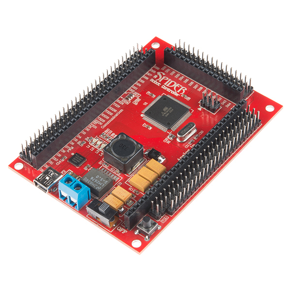
Are you ready to control all the servos? You'd better be, because the Spider Controller from Dagu is definitely ready. With a 3A switch mode power supply (capable of driving up to 48 micro servos) and the ATmega2560 MCU, the Spider Controller is perfect for 'bots requiring a large numbers of servos such as humanoid and hexapod style robots.
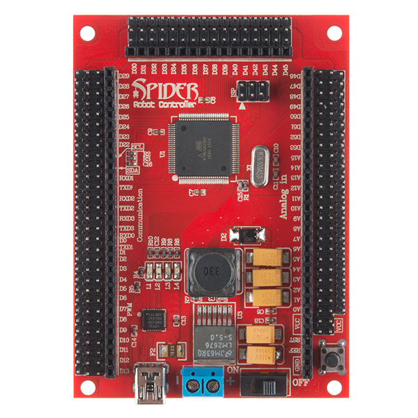
To accommodate servo connections, all of the processor's 70 I/O pins are terminated as both a female header and a servo compatible 3pin male header. Most miniature and standard servos require between 4.8V and 6V and will work happily directly from the PCB. High-powered servos requiring 6V or more should be powered via an external power source or directly from the battery.
Of course the Spider Controller is Arduino Mega compatible and can be programmed over USB using the Arduino IDE, giving you access to a wide range of programming libraries to get your robot moving!
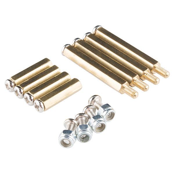
This kit comes with the Spider Controller and the standoffs to mount it. If you're looking for a servo-heavy chassis to drive, why not check out the 12-Servo Hexapod Chassis Kit in the related products below!
Note: If you're unable to compile the example code below, install the updated version of the IR library from the documents list.
- ATmega2560 16MHz CPU
- 128K FLASH, 8K SRAM and 4K EEPROM
- CP2102 USB to UART Bridge
- USB interface and ISP socket
- Built in 3A switch mode power supply (7V – 30V input)
- 70 I/O pins with male and female headers
- Support for up to 48 servos
- 16 x 10bit analog inputs
- 15 x 8bit PWM outputs
- 1 x I2C • 6x External interrupt pins
- 4 x Serial communication
- Comes with Arduino boot-loader installed
Spider Controller Product Help and Resources
Core Skill: Robotics
This skill concerns mechanical and robotics knowledge. You may need to know how mechanical parts interact, how motors work, or how to use motor drivers and controllers.
Skill Level: Competent - You may need an understanding of servo motors and how to drive them. Additionally, you may need some fundamental understanding of motor controllers.
See all skill levels
Core Skill: DIY
Whether it's for assembling a kit, hacking an enclosure, or creating your own parts; the DIY skill is all about knowing how to use tools and the techniques associated with them.
Skill Level: Noob - Basic assembly is required. You may need to provide your own basic tools like a screwdriver, hammer or scissors. Power tools or custom parts are not required. Instructions will be included and easy to follow. Sewing may be required, but only with included patterns.
See all skill levels
Core Skill: Programming
If a board needs code or communicates somehow, you're going to need to know how to program or interface with it. The programming skill is all about communication and code.
Skill Level: Rookie - You will need a better fundamental understand of what code is, and how it works. You will be using beginner-level software and development tools like Arduino. You will be dealing directly with code, but numerous examples and libraries are available. Sensors or shields will communicate with serial or TTL.
See all skill levels
Core Skill: Electrical Prototyping
If it requires power, you need to know how much, what all the pins do, and how to hook it up. You may need to reference datasheets, schematics, and know the ins and outs of electronics.
Skill Level: Competent - You will be required to reference a datasheet or schematic to know how to use a component. Your knowledge of a datasheet will only require basic features like power requirements, pinouts, or communications type. Also, you may need a power supply that?s greater than 12V or more than 1A worth of current.
See all skill levels
Comments
Looking for answers to technical questions?
We welcome your comments and suggestions below. However, if you are looking for solutions to technical questions please see our Technical Assistance page.
Customer Reviews
No reviews yet.
FTDI?? Maybe NOT: (UPDATE) The RedBack Spider I just received from Sparkfun is different than the one pictured as a product here.
It is changed to be like an Arduino Mega2560. It has the 2560 chip AND more importantly it has the Non-FTDI "CP2102"l controller USB interface. So different drivers.
The Dagu site also shows the "old" version on their User Manual, just like Sparkfun.
So, the USB setup is different!!
Sparkfun, can you update us on this issue?? WHERE are the CP2102 Drivers??
If you are a bit green like me, you might find it helpful to know that when you connect by USB to upload a sketch you may first need to install an FTDI driver. The product literature doesn't take you through that step but Sparkfun's "How to Install FTDI drivers" tutorial will help. See also http://www.ftdichip.com/Drivers/VCP.htm. I had assumed the requisite driver would be somewhere in my Arduino drivers folder but it didn't work out that way for me. Also, product literature refers to CPU as an ATMega1280 when the product I received actually has an ATMega2560. Humming along nicely now...
What's the production quality like? From the photos of the one board, it looks like there is too much solder on the SMD parts, some components are not mounted squarely, and they didn't snap off the headers very cleanly. Are all the boards like this?
Ugh, good point. The example pics make the assembly look horrid. Any comments, SFE?
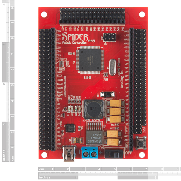
Can we get some dimensions of the board and center of mounting holes? Please?
I guess that's a "meh..."
I think the question should be "Can we get the Eagle files?", but this is not an SFE product :)
My numbers, from measuring pixels - error is 0.00725" (0.18415mm), figures are in mm (what the board's dimensions seems to be set up on) and are rounded to closest 0.5mm.
length x width = 96mm x 70mm (verified through designer's post)
Hole diameter: 3.5mm
Distance from hole center to width-edge of board, for all 4 holes: 3.5mm
Distance from hole center to length-edge of board, for switch-end holes: 2.5mm
Distance from hole center to length-edge of board, for header-end holes: 4.5mm
Just as an example of what the error margin does, that last figure could be anywhere between 4.23545mm and 4.60375mm, exact measured value was 4.4196mm.
It looks like the reset button has no solder.
Any idea when might be back in stock or something similar can be used in it's place?
It isn't till you try and build a bot with a standard arduino that you notice how nice of a design this is. Even if you aren't going with servos; with all those headers you could plug in 16 Sharp IR sensors and be covered by that 3A smps. I'd use different serial ports to keep the programming port separate from telemetry and control. 6 interupts for wheel encoders. If there was a nice red protoboard of the exact same dimensions to plug into this that would be a good combination.
What should I power this with? Do I need a set voltage or amperage? Thanks!
Needs to be between 7V and 30V and has to be able to supply 3A of current. Im using a 3300mAH 6 cell NimH battery and it seems to be working just fine.
Great! Thanks!
Is that blue thing with two holes for a battery? I have no idea what it's called, but I'm pretty sure that's what it is for.
You are correct. It's called a screw terminal.
Why not use the ATmega2560- then you have 256KB-flash, 4KB-EEPROM, 8KB-RAM, 86-general Purpose I/O, 12- 16bit PWM channels, 4-URLS, 16 ADC Channels? The ATmega1280 only has 128 K of Flash.
According to another commenter, it does now.
I don't know why you listed all those features. If you read the datasheet, there is only one difference between the 1280 and 2560, the size of the flash memory available for programming.
Considering most people will never use 128K of memory, let alone 256K, the difference in price is not justified.
No one will ever use more than 640K of ram....
While this 3A power supply sounds like enough, I happen to know that the HXT900(which I see on the Hexapod kit), has a peak current draw of 1.7A... With the 12 servo were connected + a few for a turret of course, will 3A be enough for all the the servos to operate the kit, since more than one servo is used at the time?
You are correct that if all the servos were under heavy load then 3A would not be enough. When walking, most servos are under a very light load. Even those supporting the weight are not that heavily loaded.
These servos are not HXT900 servos although the performance and strength of the gears are similar.
Mind = Blown
Typo: "Are you ready to control all the servos?" should be "Are you ready to control ALL the servos?"
hehe. CONTROL ALL THE THINGS!
Exactly. You should link the first line of the product description to this: http://cdn.memegenerator.net/instances/400x/29003982.jpg