- Home
- Product Categories
- Biometrics
- Pulse Sensor

Heart rate data can be really useful whether you're designing an exercise routine, studying your activity or anxiety levels or just want your shirt to blink with your heart beat. The problem is that heart rate can be difficult to measure. Luckily, the Pulse Sensor Amped can solve that problem!
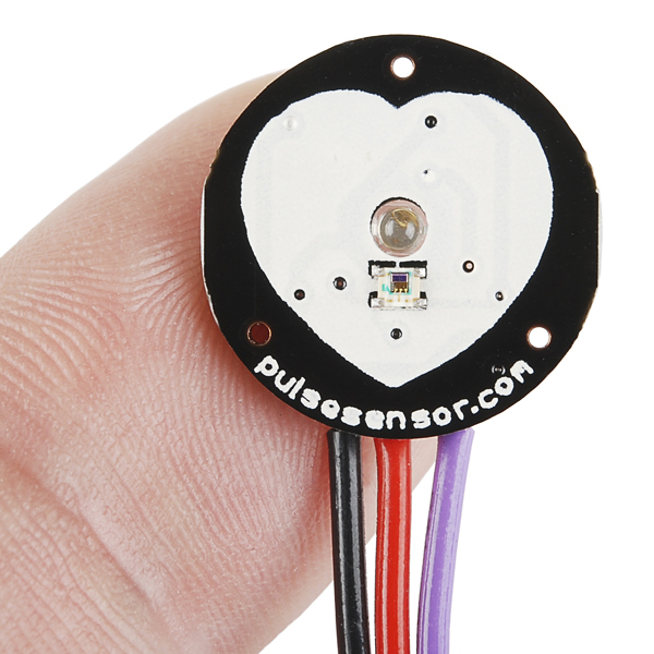
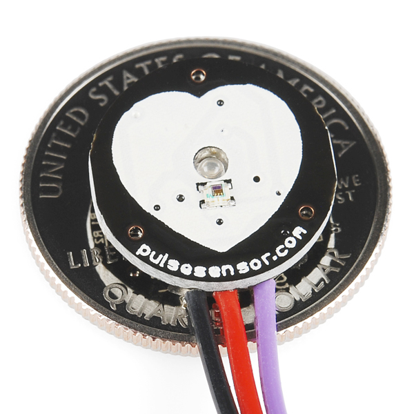
The Pulse Sensor Amped is a plug-and-play heart-rate sensor for Arduino. It can be used by students, artists, athletes, makers, and game & mobile developers who want to easily incorporate live heart-rate data into their projects.It essentially combines a simple optical heart rate sensor with amplification and noise cancellation circuitry making it fast and easy to get reliable pulse readings. Also, it sips power with just 4mA current draw at 5V so it's great for mobile applications.
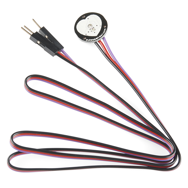
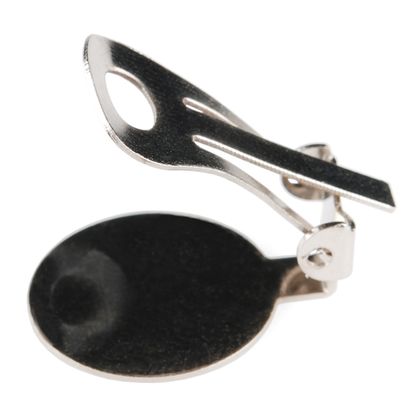
Simply clip the Pulse Sensor to your earlobe or finger tip and plug it into your 3 *or *5 Volt Arduino and you're ready to read heart rate! The 24" cable on the Pulse Sensor is terminated with standard male headers so there's no soldering required. Of course Arduino example code is available as well as a Processing sketch for visualizing heart rate data.
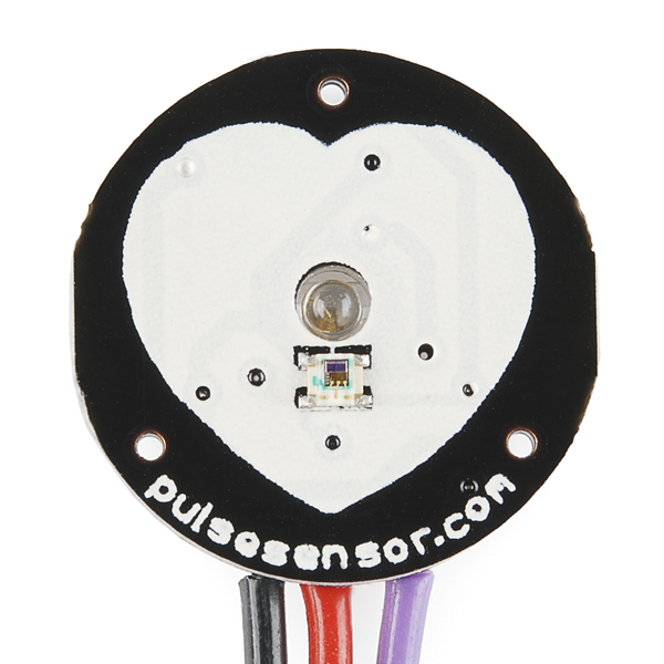
- Pulse Sensor Board
- 24-inch Color-Coded Cable with Standard Male Headers
- Ear Clip for Earlobe Heart Rate Measurement
- Velcro Finger Strap
- Transparent Stickers to Protect Sensor
- 0.625" Diameter and 0.125" Thick
Pulse Sensor Product Help and Resources
Compatible Microcontrollers (for example sketch)
The v1.4 example code for the Pulse Sensor was designed to be used with an Atmega328P’s interrupts. You can have issues with the example code when using different microcontrollers. I had compile errors when trying to use the example code on these microcontrollers: Atmega32U4 on the Pro Micro 5V/16MHz, Pro Micro 3.3V/8MHz, FioV3, LilyPad Arduino USB - ATmega32U4, Arduino Leonardo, Arduino Yun; SAM3X8E on the Arduino Due; SAMD21. There were issues compiling the example code because the pulse sensor’s code was expecting to use the interrupt timers defined for the Atmega328P.
Selecting COM port in Processing
To use the pulse sensor with the processing sketch, you need to upload the Arduino example code first.
Then, in the processing sketch, you need to change the 0 in the array where it says:
new Serial(this, Serial.list()[0], 115200);
The processing sketch will output the COM ports available in an array.
This is a common example of the enumeration on a desktop computer:
Serial.list()[0] = COM1
Serial.list()[1] = COM2
Serial.list()[2] = COM33 // this is our sensor
In this instance we change the example code to say:
new Serial(this, Serial.list()[2], 115200);
Note: Many laptops will have your sensor in the [0] position naturally
Core Skill: Electrical Prototyping
If it requires power, you need to know how much, what all the pins do, and how to hook it up. You may need to reference datasheets, schematics, and know the ins and outs of electronics.
Skill Level: Rookie - You may be required to know a bit more about the component, such as orientation, or how to hook it up, in addition to power requirements. You will need to understand polarized components.
See all skill levels
Comments
Looking for answers to technical questions?
We welcome your comments and suggestions below. However, if you are looking for solutions to technical questions please see our Technical Assistance page.
Customer Reviews
4.3 out of 5
Based on 15 ratings:
2 of 3 found this helpful:
Works great... IF you use the latest code!! (link in item description is out of date)
I couldn't get this device to work consistently using the example code in the product description. (the 1dot1 version). If you look on the manufacturer's github repository you will find a "1dot4" version which seems to pick up the pulse signal MUCH faster, and without having to position your finger JUST right. It also seems to filter out false signals much better than the 1dot1 code.
Latest code:
https://github.com/WorldFamousElectronics/PulseSensor_Amped_Arduino
0 of 2 found this helpful:
A great little device
A very little device with a vehe only thing to improve is the glue of the velcro pad.
Elegantly simple, and relatively durable
Got the Arduino code (1dot4) and Processing app (1dot1) working just fine, with only a small tweak required in the Processing app to identify my correct Serial port.
I don't have a lot of high-impact activities planned for this, but it seems sturdy enough for my uses. The kit instructions encourage you to use copious amounts of hot glue on this to attach accessories and make it sturdier and water resistant, so I think it could work well even for experiments that involve some wear and tear.
The only disappointment: the code required to run this is a lot more involved than I'd anticipated. Turns out it's trickier than I thought to measure pulse rate, and involves a lot of interrupts and custom code that's well beyond my abilities to write from scratch! So, unless you're an electrical engineering guru, expect to be sticking with the stock sample code.
Great, but pricey.
This pulse sensor is pretty good and it accurately captures and displays the pulse waveform when used on the finger or the wrist. The price seems a bit steep though. Looking at the schematic which consists of one op amp, one photodiode, and one LED, this should go for under $20.
Worked Perfectly
I needed this sensor for a school project. It worked perfectly with my Arduino Esplora and was very easy to use.
Very cool little device.
I picked up a couple pulse sensors for use with an Arduino project, and have found them to be pretty reliable. They've shown a tendency to detect beats that aren't there when jostled, despite a thoroughly rigid layer of hot glue on the back and around the connections. On the off chance that this is a power issue on my part, I'm adding a cap to the circuit, just in case.
The library uses the same timer as the tone() library (Timer2), so I had to adapt it to work with Timer1. This wasn't a big deal but might be a lot to ask of an arduino or microprocessor newbie.
Works pretty well
This pulse sensor works as advertised, but it's a little "janky" at times. Sometimes it starts picking up the wrong rhythm somehow and you have to readjust your finger so that it finds your heartbeat again.
0 of 1 found this helpful:
Wildly inaccurate
Don't waste your money on this sensor. I am using the most recent version of the demo code. I verified the accuracy of this sensor against a TomTom Spark heart rate monitor watch which also uses an optical heart rate sensor. I also verified the sensor against a Garmin workout watch that uses a heart rate monitor embedded in a chest strap. I have validated both of these watches against an EKG machine I have in the surgical simulation lab at the university where I work. The accuracy of these two workout watches are statistically "equivalent" to the more accurate EKG.
When this sensor is attached to your finger, the output isn't horrible. The intraclass correlation coefficient between the sensor and the TomTom watch was statistically significant, indicating that the sensor is sufficiently accurate. However, I wanted to use this sensor to measure heart rate as a function of surgical task difficulty. To do the surgical task, you gotta use your hands... so mounting this sensor on a finger won't work. I used the included ear lobe clip and ran a validation test. The sensor reports readings that vary between 10 BPM and 200 BPM over a 60-second time period. The intraclass correlation coefficient is essentially zero... indicating that it is wildly inaccurate. I tried mounting this optical sensor on the back of my wrist (the same place where the optical sensor in the TomTom is located) and this sensor isn't accurate. I tried mounting this sensor to the underside of my wrist and that didn't help accuracy. I tried putting it over my heart and that didn't help accuracy.
If you want a cutesy sensor that does various non-important tasks based on some estimation of heart rate, this sensor is fine. But if you need accurate data... keep on looking.
Hello!
This device is really typically used more in hobbyist environments. The accuracy can be varied widely depending on which position that you use them in.
Making sure that you're using the most recent version of the pulse sensor code can help increase accuracy as well. https://github.com/WorldFamousElectronics/PulseSensor_Amped_Arduino/tree/master/PulseSensorAmped_Arduino_1.5.0
Great sensor!
The hardware on this sensor is excellent, and gives you the ability to get started coding to access more complex biodata from the heart. Of course a photopleth isn't as accurate as an EKG/ECG but this is about as accurate as a pleth gets in my opinion!
I havent try on this sensor
Sparkfun service is incredibly amazed me. International purchase has no problem at all. The parcel arrived within a week. And yet early than estimated . All the components were packed nicely and sealed . I'm really happy with the service. Definitely will purchase on sparkfun with my next project. Thank you so much.
Works as expected
Using the Getting Started Guide and the example code, I got everything working in a few minutes. I haven't been able to use it in my actual project yet, but with the example code it should be pretty easy.
Exactly what you would expect it to be
Currently working on a project taking pulse information and sending it to Max MSP through Arduino Uno. Works great so far!
0 of 2 found this helpful:
Nice compact sensor
With its small frame it can fit in most projects. Drawback is that it is a bit limited in functionality.
As advertised
Got it connected to a raspberry pi, works like a champ
If I need readings from wrist, will it work?
I've been testing these out, and it appears that the power consumption is much higher than advertised. It says in the description that it draws 4mA @ 5V, however I am consuming 15mA @5V, 13-14mA @3.3V, which is much higher than expected. The sensor is worn during this, so I don't think it's from amplifier saturation. This happens consistently for long periods of time, so I don't think it's a fluke, and I just tested it on a brand-new, freshly set up sensor, so I don't think it's the sensor itself.
Is there something I'm doing wrong, or is this normal? This is for a battery-powered application, so it's important that it is as low power as possible.
Hi, I already bought this sensor and trying to do the connection with servo by bluetooth (slave-master) which really worked for my prototype but my servo (tower pro-SG90) which is so loud and I guess not enough to imitate the heart beat. Can I ask you which kind of servo are you using in heart shape? If you have can you send a link of the servo you are using?
Can this be used on the wrist?
Great product, but is there any sense of why the cost? This is an ADC and an amp after all. I noticed on the mfg. site they have a photo of the makershed store listing it for $20, but when you click through to the product page it's $25. I've never complained about Sparkfun's pricing, but doesn't this seem excessive for this board?!
I usually think that Sparkfun prices things very appropriately, especially their breakout boards. However, I must agree with you that this is rather overpriced. If this had even an ATTiny to serialize the output, or any "Active" component, I would accept the price. With this simple a circuit, I have to say that the cost outweighs the features.
The opAmp it;s an ACTIVE component !!!!
Quite true, sorry, I suppose was thinking of a more complex device, something to actually average the output, a small micro or something, or perhaps even a well-tuned low-pass filter for noise suppression, but you are correct, an Op-amp is considered an active component. A 19 cent op-amp and an 88 cent light sensor still does not justify the $20 price tag, in my opinion.
Dougie im with you there man. But when ever i ask a question on the price of a product, i never get an answer. But a great product all the same! Maybe i will buy it.
It can be used on animals? serves in animals ?
Hey SparkFun, update the Arduino source code link!
https://github.com/WorldFamousElectronics/PulseSensor_Amped_Arduino
The current link points to old code (1dot1) and the latest example sketch (1dot4) is MUCH better at providing a solid pulse signal. I just re-wrote my negative review into a positive one after I tried the latest example source, it was like night and day in terms of how well it picks up my pulse. With the old example I had to get my finger on there JUST right, now it's much more forgiving and doesn't send out a bunch of junk pulses unless there's a solid consistent signal.
connect the pulse sensor to esp8266 as standalone http://www.instructables.com/id/Wearable-heart-beat-sensor-ESP8266Pulse-sensor/
What is the current consumption like? I was thinking of building a Fitbit-like device and wanted to use the smallest battery possible.
Prepared with hot glue out of the box. Readings erratic and settle on 200 no matter what.
In general I was disappointed and in top of that they didn't send the Processing Sketch and the Schematic.
This is an absolutely unacceptably horrible product! I have never been so fully disappointed in the entirety of my life. Sadly, I have received absolutely NO help whatsoever from SparkFun's technical support, and therefore the product is rendered useless. It broke within hours of opening the package and never worked once. Don't buy this product. PERIOD.
I Must say i have to agree with you Ami ! what a waste of good money! sesnor doesnt work the demo code doesnt work , and when you go to supplier website pulsesensor.com geuss what there is no " contact us" details you are left to post in the forum to which no one responds
We are trying to program this product. All we need is to hook the sensor up to the Arduino and have it read and print someone's heart rate. Can someone please just post the code? Thanks for the help!
Does anyone know if the example code here can be used with the fastLED library? I've got the fastLED library set up on my micro (same as leonardo) to run the WS2801 addressable LED strips and I'd love to have a heart rate sensor to control colors or fading.
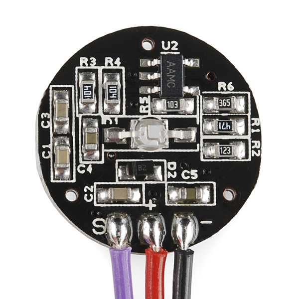
My project uses an Arduino with built in analog and digital I/O, two LEDS two resistors, USB serial communication, and heart pulse sensor. The processing is using “Processing” software that runs on a computer. Getting started Purchase the Arduino kit Purchase the Pulse Sensor Install the Arduino sketch software on a computer Download the sketch for the Pulse Sensor from the internet Download and install the processing code to your computer from the internet Download and install the Processing runtime software to your computer from the internet Upload the Pulse Sensor sketch to the Arduino Wire the Arduino to the Pulse Sensor and to two LEDs. Test using the LEDs and an Oscilloscope while using your own pulse. General wiring and setup Notes: RED wire = +3V to +5V BLACK wire = GND PURPLE wire = signal (analog pin 0 in Arduino code)
Plug the Pulse Sensor into Power (RED wire = +3V to +5V), Ground (BLACK wire), and Analog Pin 5 (PURPLE wire = signal). Pulse Sensor PURPLE wire goes to Analog Pin 5 Arduino code designed to fade an LED on Digital Pin 11 Arduino code designed to Blink pin 13 to a LED with the pulse.
General Hardware Notes:
RED wire = +3V to +5V BLACK wire = GND PURPLE wire = signal (analog pin 0 - in Arduino code) Arduino code designed to fade an LED on Digital Pin 5 Arduino code designed to Blink pin 13 with pulse
Processing setup -1 https://learn.sparkfun.com/tutorials/connecting-arduino-to-processing
Processing: The Pulse Sensor comes with code for on screen processing. This processing runs on a computer that is communicating serially to the Arduino processor that is getting analog input from the pulse sensor as input. Processing: To listen in on what the Arduino sketch is sending, Processing is used and comes with a Serial library designed for it.
To download “Processing”, go toProcessing.org and download the latest version for your operating system. https://learn.sparkfun.com/tutorials/connecting-arduino-to-processing
Once Processing is installed, open processing.
It looks allot like Arduino. The Arduino software was actually based in part on ”Processing” open-source.
Tips and Tricks Make sure baud rates match Make sure you’re reading off the correct port in Processing - there’s a Serial.list() command that will show all the available ports to connect to. If you’re “using the serialEvent() method, make sure to include the port.bufferUntil() function in your setup() method.” (learn.sparkfun.com). Be sure that whichever character you’re buffering until you see the end of line (e.g., ‘\n’), be sure that you’re actually sending from Arduino. If you want to send over a number of sensor values, it’s a good idea to “count how many bytes you’re expecting so you know how to properly parse out the sensor data.” (learn.sparkfun.com).
Reference: https://learn.sparkfun.com/tutorials/connecting-arduino-to-processing
To create a font to use with Processing, select "Create Font..." from the Tools menu. This will create a font in the format Processing requires and also adds it to the current sketch's data directory.
Processing setup-Eclipse
STEP 1. DOWNLOAD AND INSTALL ECLIPSE Grab “Eclipse IDE for Java Developers” from http://www.eclipse.org/downloads/. When you first run eclipse, it will ask you for a workspace directory. This is the directory where you will store your project files so pick something reasonable that you will remember. STEP 2. CREATE A NEW PROJECT. If you see a Welcome screen, go ahead and close it. Then go to FILE –> NEW PROJECT and select “Java Project.” Click next. Enter your project name (for example, “TestProcessing”) and select “Finish.”
STEP 3. IMPORT THE PROCESSING LIBRARIES Eclipse doesn’t know anything about Processing so we’ll have to go and get the Processing libraries ourselves. One way to do this is by pointing Eclipse to Processing’s “lib” directory or it’s a good idea to copy the necessary Processing files into the project folder itself so that everything stays together. Go to:
FILE –> IMPORT –> GENERAL –> FILE SYSTEM.
Click next. Click browse and find the Processing application. On Windows look inside the directory called “lib”, but on Mac (for Processing 1.0=) and go inside the application’s “package contents”: Processing->Contents->Resources->Java. Select the file “core.jar” inside the lib (PC) or Java (Mac) folder.
url: https://www.sparkfun.com/products/11574 browser: Mozilla/5.0 (compatible; MSIE 10.0; Windows NT 6.1; Trident/6.0) Department: general
Hey anyone used this with the a SoC x86 board? Is it possible?
If you solder the ends to an audio plug can you record the signal in a program such as audacity or do you need the arduino code? Thanks
You would need something to power the device, but other than that it looks like it's an analog output device so you theoretically could hook it up to a microphone jack with appropriate circuitry. Given the need for power and the greater flexibility, though, I'd stick to a microcontroller-based approach.
how can i buy this sensor?
Here, on SFE.
Heh! This is a really fun thing. I got it working with an Arduino, a 9V battery, and the Open Heart Kit from Maker Shed ( http://www.makershed.com/products/open-heart-kit ). Video with source code links is here ( https://www.youtube.com/watch?v=guZ9PStlZfk ).
IBI and BPM flip flopped in "PulseSensorAmped_Arduino_1dot2.ino" (from "Pulse Sensor Amped 1.2" project) and "SerialEvent" (in "P_PulseSensor_06" Processing project), downloaded from PulseSensor.com.
The following is in "SerialEvent" Process project : ...
and the following is from "PulseSensorAmped_Arduino_1dot2.ino" : ...
You'll notice the ".ino" file sends a prefix of 'B' with BPM and 'Q' with IBI and the "SerialEvent" is expecting a prefix of 'Q' with BPM and 'B' with IBI.
Not sure if Sparkfun's libraries have the same error, but it's worth a look just in case. Change your code accordingly. (Sorry about the formatting.)
does anyone know the c code of pulse sensor for stm32f4 discovery?
Is there a way to use this as a pulse oximeter?
Check out my C code port for the pulse sensor: code
Check out my C code port for the pulse sensor: http://www.libstock.com/projects/view/951/pic-heartrate-monitor
I have ported the arduino code for PIC microcontrollers you can find it at: www.libstock.com/projects/view/951/pic-heartrate-monitor
Hi people! I just got myself few of those sensors. I discovered that when attached to the body (finger or a bit above the wrist) when I move a bit there are massive disturbances in the signal, any suggestions? How it is when it is attached to the ear? Is it also so sensible to movement? Do you know some other sensor that is not disturbed by movement and gives reliable signal?
Thanks
--Zeos
This is junk. I bought 3 of these and could never get them to work. The Arduino code does not even work on stock UNO. Their website is totally bogus and just spits ads at you. Other people on their forum complained that the device did not work but nobody ever replied with a fix or even a comment. To add insult to injury if you decide to post on the forum you have to endure listening to some useless 12 second ad (Progressive insurance !) so you can get the capcha code to submit the comment. What a joke ? A support forum is there to support users not to generate revenue for the site. Complete waste of $ 75.
We have purchased 3 sensors, and only 1 of them had defective hardware. The others worked fine with the code samples, pretty usable right out of the box.
can this sensor be used on wrist?
Can the sensor read heart rate under the wrist?
Would this sensor cause any problems for people with pacemakers?
Not at all. This sensor works via reflected light, and involves no electrical connection to the subject.
Can this sensor work with IOIO-OTG? if so, I need the codes.
Yes it can work with any 3.3V or 5V microcontroller.
I need a heart rate monitoring hardware. Is this sensor stable and accurate? Can i trust its result? I was planning the buy an ECG sensor from cooking-hacks. Can anyone help me?
And can i use this sensor with raspberry pi?
Can this product work using IOIO-OTG??
I think that the sensor that I received was defective. I tried running the example Arduino code, using several different Arduino boards, placing the sensor at different locations on my skin, and the measured heart rate fluctuated between 2 and 3 times the actual value (measured from another device).
If you're concerned with the functionality of your sensor, please contact techsupport@sparkfun.com and they will be able to assist you further.
Hi, I just bought this sensor and was wondering if I can use it with the "Logomatic v2 Serial SD Datalogger"?
can i use this for ECG measurements?????
Anybody tried this on small rodents (e.g., clipping to ear to read heart rate; this is for a research lab)?
I have a dog, and I have tried, but he shakes it off his head and then tests it's flavor! You will really need to test various anatomy of rodents. Works best with capillary tissues. My first thought would be to select a part of the anatomy that wouldn't contribute much movement noise, then shave the area, and attach the sensor with a double-stick tape. Crazy! Might work. Ear is possibility, but the ear membrane is rather thin. Worth testing... and easy to test, with the Pulse Sensor! btw, i am part owner of Pulse Sensor
Nice unit
3 AA batteries and your PC soundcard's line-in to a software oscilloscope (http://www.zeitnitz.de/Christian/scope_en is excellent) serve nicely as a substitute for the Arduino.
Hi Please tell me if I can connect it to my 8051 microcontroller ?
I was wondering if there was an alternative to using HOT GLUE to protect the "back" of the sensor? A week ago I purchased a sensor and it worked great. Until I put the recommended hot glue on it. Since then it stopped working. I attempted to remove the wad of hardened hot glue and some of it remained embedded. (and no...there was no glue obscuring the LED on the front.) I don't want to go into the pro and cons of buying microcircuitry that requires the end user to protect the product with hot glue...but I would love to know if there was another way to accomplish the same goal. I have purchased a replacement and I am loathe to throw another 30$ away on a third. This is for a science project and time is running out...
Thanks
I've got one of these at the moment, and other than hot glue, the best I can think of would be clear heat shrink wrap. You'd have to make sure the heat used didn't cause components to slide- I'd be afraid of the heat loosening the solder joints. Other than that, it should be fine I would think. Just make sure that the front side is flush and clear, as the cloudier the material, the harder it will be for the light sensor to do it's job.
I built one very simple unit using a red LED and sparkfun's TEMT6000 light sensor connected straight to ADC. Check out my blog post: simple pulsoximeter
Is there any way to use this as an oximeter too?
I don't believe so, pulse oxymetry requires two wavelengths (red and IR) and measuring the difference between them.
FYI, there is no reason this should be limited to the earlobes or fingers. Reflexive pulse oximeters like these can typically be applied anywhere there isn't too much muscle, such the toes, throat, forehead, or chest.
The chest is often the best option, in fact. If the wearer is cold, has poor circulation, and/or is shivering, most other placements return inaccurate values due to vasoconstriction and vibration.
Maybe it's because the velco strap (or ear clip) is most easily attached to either the ear lobe or finger. I'd be interested in seeing it work on the chest.
Are there any data sheets with specifications on current (amps) in addition to voltage (+3V to +5V in on red wire)? I would like to know the lifetime if connected to an external power source (batteries). I already checked their home page, but to no avail. Thanks!
Current consumption of the sensor is ~4mA
The green LED takes about 20mA. I'm looking for a lower power solution, anybody experimented with lower power LED's?
The LED will use all the current it can, that's why LEDs need a current-limiting resistor. This design has a 470ohm resistor. If I make a very wild guess (knowing it's a green LED) that the voltage drop through the LED will be about 2.4V, and we know I (current) = V (voltage) / R (resistance), we get I = (5.0V-2.4V)/470ohm = ~5.5mA, which isn't far off the given current spec. Generally, the max current spec of an LED is an absolute limit. You can run it anywhere below that :)
I highly recommend that if you use this device that you tack TVS on the IC pins or pot the entire circuit with some kind of clear epoxy. ESD protection was not even considered in this design.
The Microchip op-amp is ESD rated, so it'll be hard to kill. The kit comes with clear plastic stickers to cover the exposed photosensor chip, which will give it some protection. And the whole thing is reverse polarity protected too.
For a fascinating description of the development of this product, check out this page.
Must emphasize that it is not advised to pot the circuit in clear epoxy! Doing that will likely cover the LED in epoxy, and will add lensing to the LED which can kill the Pulse Sensor functionality. If you must pot the Pulse Sensor, be very careful. The Getting Started Guide has useful tips for sealing the front and back. RSP, you are right about the ESD. Those Microchip op-amps are tough buggers. (disclosure: i am one of the guys behind Pulse Sensor)
The Processing Code gives me compile errors. whats the problem?