- Home
- Rover 5 Motor Driver Board

Rover 5 Motor Driver Board
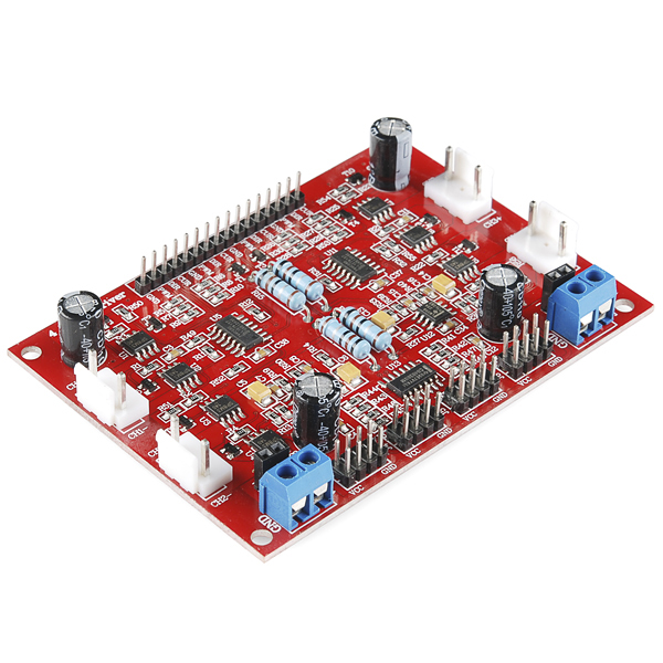
This motor driver board, originally designed by Dagu for their Rover 5 platform, is ideal for any small 4-wheel drive robotic vehicle. With four motor outputs, four encoder inputs and current sensing for each motor, it's a must-have when implementing omni or mechanum wheels.
The motor drivers can be controlled by simply applying a logic 0 or 1 to the direction pin for that motor and a PWM signal to the speed pin. In this way, the speed and direction of four separate motors can be controlled independently from only 8 GPIO pins. The encoder inputs on the driver board mix each pair of encoder inputs using an XOR gate making it possible to read both inputs from a quadrature encoder using only one interrupt pin.
Reading the current sensor output is easy, each current sensor pin will output about 1V for each Amp of current drawn by the associated motor up to 5V. Connect the current sensor pin to the analog input of your controller and you'll be able to detect stalls and other motor problems.
There are two power connectors on board. One is for 5V logic and the other is the motor supply. Be sure to turn on your logic supply before applying the power source for your motors. The board is rated for a maximum motor supply voltage of 12V.
- 4 Channel Motor Driver Board
- Mounting Hardware
- 4 x Low Resistance FET “H” Bridges
- Each Channel Rated for 4A Stall Current
- Easy-to-Use Control Logic
- Current Monitoring for Each Channel.
- Quadrature Encoder Mixing Circuitry
- [User Manual](http://cdn.sparkfun.com/datasheets/Robotics/4 Channel instruction manual.pdf)
- GitHub
Rover 5 Motor Driver Board Product Help and Resources
Core Skill: Robotics
This skill concerns mechanical and robotics knowledge. You may need to know how mechanical parts interact, how motors work, or how to use motor drivers and controllers.
Skill Level: Rookie - You will be required to know some basics about motors, basic motor drivers and how simple robotic motion can be accomplished.
See all skill levels
Core Skill: DIY
Whether it's for assembling a kit, hacking an enclosure, or creating your own parts; the DIY skill is all about knowing how to use tools and the techniques associated with them.
Skill Level: Noob - Basic assembly is required. You may need to provide your own basic tools like a screwdriver, hammer or scissors. Power tools or custom parts are not required. Instructions will be included and easy to follow. Sewing may be required, but only with included patterns.
See all skill levels
Core Skill: Programming
If a board needs code or communicates somehow, you're going to need to know how to program or interface with it. The programming skill is all about communication and code.
Skill Level: Rookie - You will need a better fundamental understand of what code is, and how it works. You will be using beginner-level software and development tools like Arduino. You will be dealing directly with code, but numerous examples and libraries are available. Sensors or shields will communicate with serial or TTL.
See all skill levels
Core Skill: Electrical Prototyping
If it requires power, you need to know how much, what all the pins do, and how to hook it up. You may need to reference datasheets, schematics, and know the ins and outs of electronics.
Skill Level: Competent - You will be required to reference a datasheet or schematic to know how to use a component. Your knowledge of a datasheet will only require basic features like power requirements, pinouts, or communications type. Also, you may need a power supply that?s greater than 12V or more than 1A worth of current.
See all skill levels
Comments
Looking for answers to technical questions?
We welcome your comments and suggestions below. However, if you are looking for solutions to technical questions please see our Technical Assistance page.
Customer Reviews
5 out of 5
Based on 2 ratings:
Great Driver Board
I was able to use this product along with the Rover 5 Chassis, among other things, to build this cool step climbing Robot https://youtu.be/LcFL2Xf_sUM
I'm curious if this can work with the logic supply at 3.3v instead of 5v. If it does work, How does that affect the current sensing analog output?
Do you got any answer on this?
So the answer is yes, tested myself with a 3.3V logic and with a 5v logic, measured the velocity of the wheels, and they are the same.
Example code and hookup with an Arduino Uno, the Rover 5 Chassis, and Rover 5 Motor Driver => http://arduino.cc/forum/index.php?topic=82618.0
Guys any idea what kind of JST connector are white motor connectors?
You can use this connector on the motor side (with 3 contacts, the photo is not correct): http://canada.newark.com/jst-japan-solderless-terminals/vhr-3n/wire-board-connector-rcpt-3pos/dp/68C2105
Anyone know what is the correct connector for the motors? This one listed here is not correct.
Needs a complete kit SKU with platform/arduino.
Just curious why you didn't make it a shield?
Sam
This isn't a product SparkFun manufactures. They just carry it.
Although it does not plug into the Spider controller like a Shield it is the same size with the same mounting hole spacing. The spacers included with the motor driver allow the Spider controller to stack neatly above it with room for female to female jumper wires to link the PCB's.
As the Spider controller has 6 external interrupt pins available you can have 1 interrupt monitor each motor making it ideal for the mecanum wheels.
Check out my Mecanum wheel puppy robot to see this motor controller in action with a Spider controller. http://www.youtube.com/watch?v=r-V2uHWQObI
The manual for this board says not to exceed 4.5A, and I have motors that state a max. stall current of 4.9A @ 12VDC. Will that extra 0.4A really cause problems if I were to stall the motors using this board? Is there anything I can do to let me safely use my motors with this board?
What you can do is use a lower voltage supply. Since the stall current of a motor is a function of it's DC Resistance you can actually figure out what voltage you should run to get them just below the 4.5A limit:
4.5A/4.9A * 12V = ~11V. If you make sure your motor supply is under 11V then you shouldn't be able to exceed the max stall current of the driver board (I'd recommend 9V for safety and because it's a common voltage). This does mean you're limiting your maximum speed by about 25% (at 9V).
can we use this chassis for a stand alone robotic frame? givin it has space for 4 motors and four encoders?
is their a reason why my msg shows up in the middle of 2 years worth of other msg's?
Comments are sorted by number of stars and recency, in that order, per level. So right now your comment has 1 star, which puts it below all the 4-, 3- and 2-star comments. It's also the most recent, which puts it above the older 1-star comments. Don't worry, your question will still likely be seen by people who know the answer :) I'm not one of those people, though - I'm one of the people who wonders if you're confusing this product (a driver board) with a different one (chassis), but might be inclined to point to http://forum.arduino.cc/index.php?topic=82618.0 mentioned in the 3-star comment :)
On the "4 Motor Driver" side of the board, is it possible to use just the PWM and GND pins to control the motors? Im using an APM/ Pixhawk autopilot board and it only has a PWM, VCC and GND output (typically used for servos and ESCs).
In addition to the PWM pi you also need use the DIR pin (in order to define the motor direction). So, minimal requirements for 4 motors full control are: 4 PWM, 4 DIR, board VCC, GND and motor power supply.
Hey! Has anyone tried connecting it to IOIO board?
What are this board's sizes??
How much maximum voltage it can handle
Could I connect this to an arduino and program with arduino enviroment
Yes, have fun!
Hi,
Early Last year I made a library for this controller. I just saw that SFE has it now and decided to post it. I posted it on Github so at least its a starting point. I am sure it can be improved but all the basic functions are there including encoders.
http://goo.gl/Nx1CTf
For info on the encoders it uses the teensy library inside of this library.
Check out and let me know what you think.
This looks great! Would you mind if we forked your library over to our own GitHub account? If so, please let me know what user name you'd want us to use in your attribution or if there's any other info you'd like us to include.
Or if you want just username put friedcircuits which is my Github username.
Sounds good! You can just put William from FriedCircuits.us. I am interested to how it improves ;). I am just getting back into the Rover5 and working on getting the BeagleBone with Arduino for the low level stuff working. I think I will be going the ROS route. Should be posting soon on http://mobilewill.us.
Thanks Toni!
Awesome! Thanks so much! I did get it forked and we should have a link on the product page soon. I can send you a little thank you gift if you message me your address to toni@sparkfun.
is there a way to get this to work with the arduino uno ? any answers would help
is the motor output voltage regulated or is it the same voltage as the motor supply voltage? The rated 7.2 V motor has a range of 5 to 7.5 V, according to the specs. So if I use 2S LiPoly, do I need to put in a voltage regulator that keeps the voltage within the spec.
Just putting this here in case it might help anyone else:
I was curious about this statement in the manual that is given with no explanation:
"The motor power supply should not be connected without first connecting the +5V for logic."
I looked around and found a concise explanation from an embedded systems book:
"Typically, the logic that controls motor H-bridge or analog amplifier operates from 5V or 3.3V. The motor power supply may be 12V, 24V, or even 50V. If the motor power supply comes up first, the inputs to the H-bridge or amplifier may be in an invalid state and the motor may jerk momentarily. In a system with a limited range of motion, such as a robotic arm, the motor may slam up against whatever limits the travel. This can be hard on the mechanical components and gears connected to the motor shaft."
Personally, I don't foresee any problems with the jerking so now I know I don't have to worry about this :)
Has anyone managed to get this working (and the rover 5 platform) working with a Raspberry Pi? Is it too difficult?
Curious as well. I saw the Raspi controller Spark has, but it can only do 2 motors :(
+1 I am also trying to figure out how to use this with r-pi. I think we'll need a multi channel PWM first, as PI has only one PWM channel available. Planning to get something like this http://www.adafruit.com/products/1455. I also wanted to know if this board can use 3.3V logic, so I don't have to buy a level shifter. The doc for this board is not very useful, please let me know if anyone finds any more info on this board or an example for interfacing this with pi.
Did anyone get this Rover 5 board working with an RPi? There is a young person I am mentoring who already has a Pi and Gertboard and a Rover 5 robot, and I am trying to determine a path forward for him to interface from the Pi to the Rover 5.
I put 11V into the logic supply, released a bit of the magic smoke, any idea which component (or some tips on finding out) might have blown? Wasn't my brightest moment but the labeling is kinda crappy.
Is there a minimum motor supply voltage?
What should the frequency of the PWM signal be? What voltage? I didn't see ether of these things mentioned in the documentation.
Does this mount to the top of the Rover 5?
Sort of. Looks like the board doesn't take full advantage of the mounting struts in the Rover 5. Check out a picture of this board (and an arduino board) mounted to a Rover 5 in this forum thread: http://arduino.cc/forum/index.php?topic=82618.0
What are the exact dimensions for the spacing and size of the mounting holes?
Can this be controlled by an Arduino UNO?
Yes it can :)
http://arduino.cc/forum/index.php?topic=82618.0
really important. can you use 2 channels in parallel to get more current?
same question !!!!!!
Does this board come with back EMF protection?
The SP8M3 FET's have built in flyback diodes.