- Home
- Product Categories
- 7-Segment
- SparkFun OpenSegment Serial Display - 20mm (Blue)

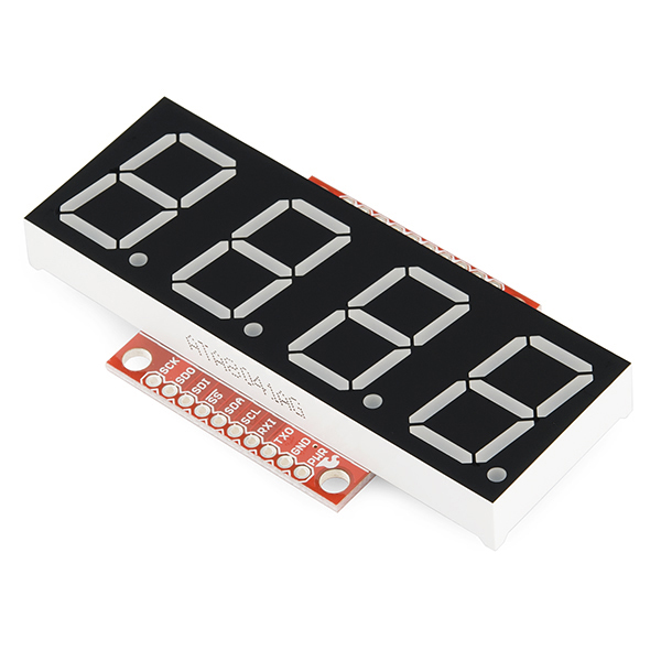
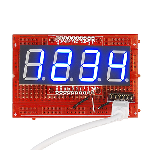
SparkFun OpenSegment Serial Display - 20mm (Blue)
OpenSegment makes it easy to add a large 7-segment display to your project. Because larger 7-segment displays pull more power than a microcontroller is able to drive directly, the OpenSegment has 8 PNP and 4 NPN transistors in order to drive the segments at their maximum brightness!
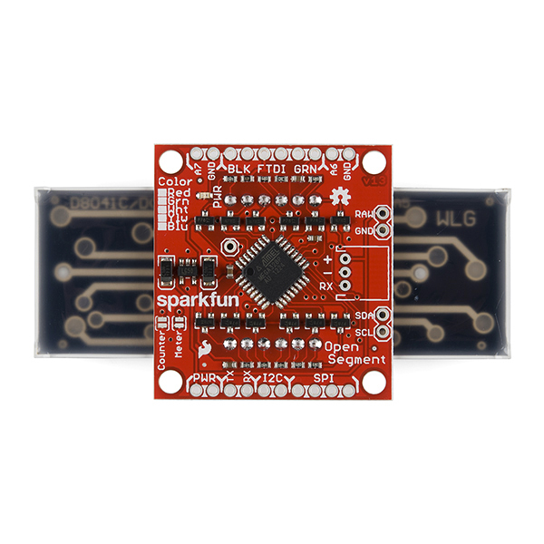
The on-board ATmega328 receives data over multiple digital interfaces (such as TWI, UART and SPI) and does all the PWM and upkeep of the display so your main controller doesn't have to. There are even two built-in functions that can be activated with solder jumpers. The counter function simply counts up or down, incrementing when you pull down SDO and decrementing when you pull down SDI. The meter function gives you a voltage read-out of the ADC!
OpenSegment runs at 5V and uses a standard FTDI connection for programming. The board is pre-flashed with a bootloader compatible with the Arduino Pro Mini @ 8MHz setting under the Arduino IDE. This firmware is an updated version of the Serial 7-Segment firmware designed to run on both devices. The commands will be largely the same except, of course, that this display only has decimals and no colon. See the datasheet for the Serial 7-Segment below to get an idea of the serial command set.
- On-board Transistors Allow Display to Run at Full Brightness
- Serial Commands Available to Adjust Brightness, Baud Rate, and I2C Address
- Individual Control for Digits and Decimal Points
- Arduino Compatible with FTDI Header
- Built-in Meter and Counter functions
SparkFun OpenSegment Serial Display - 20mm (Blue) Product Help and Resources
Core Skill: Soldering
This skill defines how difficult the soldering is on a particular product. It might be a couple simple solder joints, or require special reflow tools.
Skill Level: Noob - Some basic soldering is required, but it is limited to a just a few pins, basic through-hole soldering, and couple (if any) polarized components. A basic soldering iron is all you should need.
See all skill levels
Core Skill: Programming
If a board needs code or communicates somehow, you're going to need to know how to program or interface with it. The programming skill is all about communication and code.
Skill Level: Rookie - You will need a better fundamental understand of what code is, and how it works. You will be using beginner-level software and development tools like Arduino. You will be dealing directly with code, but numerous examples and libraries are available. Sensors or shields will communicate with serial or TTL.
See all skill levels
Core Skill: Electrical Prototyping
If it requires power, you need to know how much, what all the pins do, and how to hook it up. You may need to reference datasheets, schematics, and know the ins and outs of electronics.
Skill Level: Noob - You don't need to reference a datasheet, but you will need to know basic power requirements.
See all skill levels
Comments
Looking for answers to technical questions?
We welcome your comments and suggestions below. However, if you are looking for solutions to technical questions please see our Technical Assistance page.
Customer Reviews
4 out of 5
Based on 3 ratings:
Really Nice Display
I purchased this display to make a clock. I have it connected to a Raspberry Pi A+ using SPI. It works great. I'm using Derek Scholten's Python library (see the link below).
I didn't notice that the display did not have a colon for time. It's not a deal breaker, but would have been nice to have.
Since the Pi can run two, I'm thinking of getting a second to display the date on my clock.
http://www.derekscholten.com/2013/09/02/raspberry-pi-sparkfun-7-segment-display-clock/
Easy to use, limited by lack of colon for clock displays
This is a relatively easy to use, affordable 4 digit display in a larger size. If you also have another Micro Controller in your project (e.g. an Arduino compatible), you can drive the display with very few I/O pins and have several protocols available. It has good library support and the only reason I didn't give it a Five Star review is that this display lacks a colon, which is nice for showing the time.
Easily met my needs for a bright, large format display
I needed a precision speedometer for my tractor. I had to be able to read the display outdoors in full sunlight, and the display had to show my speed in 10ths of MPH.
This display was easy to configure and communicate with. I especially found the cursor control and decimal control a must for my project (my project only reads out three digits, so I masked off the first digit and then offset the display mounting in the bezel.)
I would suggest to those who want a colon (such as for a clock display) get creative and wire in a surface mount LED over one of the existing decimals. With a little work you may even be able to grind a little trough in the face and mount the LED flush, but I have not tried it myself.
One thing to note is that the blue display I bought lacked contrast and was very difficult to see in bright light conditions. This may be the case with the other colors as well, and the effect is even apparent in the product photos. The lack of contrast comes from the fact the segment bezels are cast in a white/diffuse plastic which, in bright lighting, does not contrast much with the light from the LEDS.
The visibility in bright lighting can be vastly improved with the proper color filter. I keep a swatchbook of sample gel cinematic lighting filters from Rosco in my desk for just such purposes. I found that placing the Roscolux #4290 CalColor Blue sample between my blue display and the clear protective window I made gave me a beautiful bright, deep blue over "black" appearance, which is easy to see even in full and direct sunlight with the brightness set at 75%.
It is interesting to note that even though the filter I used only transmits 15% of the light, the portion it sends through at about 400 nm is such a good match that the display ends up appearing much brighter.
Swatchboooks can be bought for a few dollars from places such as stagelightingstore.com and others. As I said, they are handy for all sorts of optics and lighting projects and even include several frosted and diffusion type samples.
I would guess that all of these Open Segment displays would benefit from the proper filtering.
All in all, I am very satisfied with this display and I cant wait to find an excuse to use one in a future project.
I wish I could copy/paste this information in the review sections for the other colored Open Segment displays, as I think it might be useful to others, but it does not look like I can post a review without actually buying the product. Maybe if one of the SF staff sees this they can copy it over to the others??
Rob
There is some ambiguity in the documentation and comments in the sample code about the brightness setting. It appears the value is a percent (0 to 100) instead of 0-255. I wanted half brightness, but 128 gave me full brightness. 50 gave me half. From the firmware, it looks like anything over 100 is considered full brightness.
You have to go digging but the SetBrightness() function expects a brightness from 0 to 100. 128 would be rendered as 100% brightness.
I believe the documentation was written prior to a firmware change. Docs have been updated.
Thanks for updating the docs. On the "Special Commands" page, the brightness section is now correct, but the table at the top of the page still refers to a 0-255 brightness value.
Dah! Right you are. Thanks! Updated.
At least for the I2C mode, this is the worst documentation I have ever seen. There is no mention anywhere of max clock speed, if pull-up resistors are needed or even a sample command using I2C. Has anyone got this to work and can at least explain how the device address byte with the standard R/W bit is sent to the display?
Hi Phoenix and Mark - sorry for the confusion. Datasheets often (but not always) describe the I2C address in 7-bit form. This means the user must shift the address one bit left and add the read (1) or write (0) bit to the zero bit position to form an 8-bit I2C command. In the case of OpenSegment this would translate to being the read address of 0b.1110.0011 or 0xE3 and the write address of 0b.1110.0010 or 0xE2.
I've added this note to the Getting Started guide and the example code. Sorry for killing a bunch of your time!
Unfortunately, they are focused on providing Arduino examples. While I appreciate how Arduino has made microcontrollers accessible to the masses, the oversimplification has started to creep into the worst of places, like the documentation. I would almost be willing to pay extra if they would write a straight AVR C/C++ based firmware, along with examples and documentation.
To answer your questions, you send the 7-bit address, 0x71, plus the R/W bit, with the i2c start command and then send the byte commands shown under the basic serial documentation. Pull ups are required, regardless of what the documentation states. 4.7K on both pins.
The best thing to do is to download the firmware and study it. It will shed partial light on what is going on behind the scenes.
I should mention that I couldn't get the smaller 7-Segment Serial Display to work with i2c at all, to the point of having to request a refund. I should get this display as a replacement in the mail on Monday and I'm hoping to have better luck. They use the same firmware, but I am being cautiously optimistic.
Thanks Mark - I am anxious to hear what you find when you receive this version of the display. I tried sending exactly what you mention and never got the display to acknowledge the control byte (0x71 plus the R/W bit). I also had pullup resistors on both SCL and SDA. I tried numerous variations on the control byte and never got it to do anything. On the bright side, when I gave up and switched to using the SPI port it worked the first time.
Unfortunately, no luck on this display either. I can confirm that my ATmega32 is working, but so far I cannot get this or the smaller display to work with the i2c bus. I've tried both the hardware TWI interface and software libraries across two different chips. This makes me think that this is an issue with the Arduino Wire library. I'm curious if anyone has gotten these displays to work with i2c using straight AVR C/C++. The display is just an Atmel microcontroller masquerading as an i2c device through the Arduino Wire library. That has to be the issue. I would imagine it would work if I were using Arudino, and it appears that they tested the i2c interface with an Arduino, but wonder if it was tested with an AVR without Arduino? This would be a necessary test as not everyone uses Arduino.
I'm not sure if it is possible, but I am tempted to flash over the Arduino bootloader with a custom C/C++ firmware taking advantage of the AVR's hardware UART, SPI and i2c buses. I don't trust libraries in cases like this. Too many potential issues, especially since the libraries are a software abstraction layer over hardware functionality. Who knows what is going on behind the scenes.
I was afraid of that - but on the bright side, at least I don't feel like an idiot any more. It shouldn't be this hard. Hey Sparkfun - has ANYONE out there been able to get this display to work using I2C with something other than an Arduino??? If so please let us in on the secret.
I just said screw it and went with UART. It just wasn't worth the headache and I cannot find a way to remove the bootloader. Oh, sure... Google gives plenty of sites that state it can be removed, but I have yet to find one that details how! O.o I'm not going to risk bricking the AVR since I can get it to function with the UART. Again, not worth the headache.
Still, it doesn't work as advertised and that's a problem that Sparkfun needs to address. Promptly.
Finally figured it out. I dragged out my Arduino board and used their sample code and then hooked up my Saleae logic analyzer (worth it's weight in gold, btw) to see what they were actually sending. The control byte does use 0x71 as the device address but it gets shifted one bit to the left and then the R/W bit (set low) is added in. So you end up sending 0xE2 for the control byte. So for example if you want to display the numbers 5,6,7 and 8 on the display you would send this sequence: Start - 0xE2 - 0x05 - 0x06 - 0x07 - 0x08 - Stop. If they had just shown something like this in the documentation it would have been really really helpful. I also discovered that apparently the display unit has pullup resistors for the SCL and SDA lines so you don't have to add those yourself. I don't know what the max clock rate is for the display but I was using 100Khz.
Thanks! I don't have any tools, so I would never have been able to figure that out. That logic analyzer isn't that expensive. I need to start collecting tools.
Where does this shift occur and is it part of the i2c specifications? That cannot be right.
The "shift" I mention is just something you have to do when you "assemble" the control byte for I2C commands. What was confusing to me is that for this display all the examples were done using the Arduino "wire" library and show commands like this:
wire.beginTransmission(DisplayAddress);
which is easy to use but if you are trying to understand what's really going on it's not very helpful.
The control byte is part of the I2C spec and if you are interested in learning more about I2C communication here is a link to a page that does a pretty good job of providing details on how I2C works. It is definitely more challenging than SPI but many MCUs these days have built in peripherals to handle both.
So the shift is required then? If so, that means the TWI library and software libraries I've used have a bug in them.
Well, I feel stupid! Always read the specifications!
https://forum.sparkfun.com/viewtopic.php?f=14&t=40206
Would it be possible to configure one of the outputs on the board to go logic high (or low) once a specified count is reached? I'd like to configure this to drive transistor interface to a buzzer or beeper to tell me that I have reached a specified count. I'd like to use it for a coil winder project I am building.
Cool idea and very possible. You'd have to modify the code on the unit, but that's fairly straight forward if you're familiar with Arduino and using an FTDI.
SDI and SDO are the counter pins, so you wouldn't really want to use them as the high/low output. I would recommend the *SS pin (digital pin 10 in Arduino).
You'd either need to hard-code the specified max to trigger on (97 for example) or you'd need to add some functionality so that the user could add it. None of this is tricky, just requires some custom coding.
Good luck! Let us know how your project goes.
Beware - NOT A DESIGN FAULT - BUT NO reverse voltage knucklehead protection. Serves me right trying to wire up late at night after a long day - immediately smoked on of the SMC caps I believe. Didn't fry my Intel Edison so very thankful for that.
Fooey. Sorry Bob! But thank you for reporting back when you had a problem. If we hear more reports of problems we'll consider designing in reverse polarity protection on the next version.
Is it possible to order a batch of these without the display soldered in? I want to be able to swap out multiple colors without risking amaging the board during desoldering.
Fiero79
I'm trying to download the example that comes with the sevseg github project, it basically counts up from 0. But, I can't get the sketch in to my open segment. I have Arduino Pro/Mini @ 8mhz 328 selected, when I upload, the board turns off and on but then displays a -0-9 and I see this on the Arduino IDE
avrdude: stk500_getparm(): (a) protocol error, expect=0x14, resp=0x00
avrdude: stk500_getparm(): (a) protocol error, expect=0x14, resp=0xe0 avrdude: stk500_initialize(): (a) protocol error, expect=0x14, resp=0x00 avrdude: initialization failed, rc=-1 Double check connections and try again, or use -F to override this check.
avrdude: stk500_disable(): protocol error, expect=0x14, resp=0xe0
Any ideas whats wrong? I'm using IDE 1.0.5 with the 5V FTDI breakout on USB using port /dev/cu.usbserial.
Getting the same thing here. I've tried selecting both the Arduino Pro Mini 8mhz board, as well as the "Serial 7-Segment Display" board. I've tried both 5v and 3.3v FTDI (since the Pro Mini at 8Mhz is actually a 3.3v board). Didn't seem to make any difference. Would love to hear if you find a solution.
Still stuck, does anyone monitor these comments?
Sorry we didn't catch this until now. We just found out that we have been actually programming these with the "LilyPad Arduino w/ATMega328" bootloader. Somehow our production files were mixed up, and this wasn't caught during testing because we use a combined hex file that includes both the bootloader and the firmware. We are currently working on changing our production files, but for now, if you want to upload a new sketch to your board, please select "LilyPad Arduino w/ATMega328" as your board option in the Arduino IDE. Again, sorry for this confusion and please let us know if you run into any other problems. All of our future boards will ship out with the correct "Arduino Pro Mini 8MHz" bootloader.
Ah ah! Very good. As it turns out, I was unable to flash using the Arduino 1.0.5 IDE under OSX, however the latest 1.0.5 release for Windows appears to have flashed these with the "Serial 7-Segment Display" board selected. I will try the Lilypad board under OSX next.
I have a replaced board and this still doesn't work. I've tried 3.3V and 5V and it makes no difference.
avrdude: stk500_getsync(): not in sync: resp=0x00
This is different than last times errors, see above. Has anyone managed to reprogram one of these things as advertised? Frustrated...
Still doesn't work. Same problem.
Binary sketch size: 4,700 bytes (of a 30,720 byte maximum)
avrdude: stk500_getparm(): (a) protocol error, expect=0x14, resp=0x00
avrdude: stk500_getparm(): (a) protocol error, expect=0x14, resp=0xe0 avrdude: stk500_initialize(): (a) protocol error, expect=0x14, resp=0x00 avrdude: initialization failed, rc=-1 Double check connections and try again, or use -F to override this check.
avrdude: stk500_disable(): protocol error, expect=0x14, resp=0xe0
Not sure why you are still running into issues. We sent out a freshly programmed and tested unit for your replacement. It passed all tests and programming here. We'll keep working with you over email to figure this out and get you up and running!
Sorry we missed this! We do try to keep track of all the comments, but sometimes a few slip through. Email techsupport@sparkfun and they should be able to help you with the issue you're seeing.
Your after sales sent me a new board that was promised to have the correct firmware on it. It is behaving differently. Right now, it just turns off and on and then displays 1234. The error message is:
avrdude: stk500_getsync(): not in sync: resp=0x00
That likely means that you are attempting to program it with the wrong board selected in the IDE. That's usually the error that pops up in that case.
Has anyone measured the i2c bus capacitance on these devices? I'm trying to get a series of 8 of these working on a 40ft bus and I need to calculate the pullup resistor values, if it's even possible.
Can I use my open segment serial display to display my 12v battery power? I am a novice and although it says you can plug it into a 12v power source, I am wary.
I just want it to display voltage i.e. 12.1, 11.5, whatever. I really like the display on this item, I would like to use it for power display. Any suggestions?
Kix
You can power the display with 12V but the display is setup to read from 0 to 5V (the voltage that the microcontroller runs at).
You could create a voltage divider to divide the 12V down to 5V max (R1 = 1700 ohm, R2 = 1200 ohm). You'd need to reprogram the microcontroller to 'know' the ratio and display 12V when it sees 5V. It's a good project to learn a little about dividers and microcontrollers!
Call me crazy, but shouldn't these have the colon and apostrophe? Just got a blue and all I see are the decimals for digit 0,1,2,3. I don't see the colon that would normally be between digit 1 and 2. and I don't see the apostrophe between digit 2 and 3. the docs mention apostrophe and colon control (colon control sounds funny). but, I don't see the LED's on the display. A pic of my display is here: http://research.catalinatechnology.com/Lists/Photos/WP_20131104_003.jpg
I am not so worried about it for the project that I am working on since I am just using this to display a number. but, if I wanted it for a clock, the colon would be handy.
Sorry! We didn't mean to be misleading. The product photos are always up to date but the datasheet could use some finer explanation. I started an issue. We'll get it fixed soon.
nope - no colon, apostrophe, alarm or am/pm indicators on these - just a simple 4-digit display. The 7-Segment Serial Display - Blue does offer them.
good to know. I like the size of this display. but, if I do a clock, I think I will have to go for the 7-segment. so far, this display is pretty nice (even without colon, apostrophe, alarm, etc) will be a great counter for climate monitors on kegerators, etc.
I am looking for a way to display voltage on my R2-D2. Will this work? *I am still learning.
You could certainly use this as a display in a project like that. However, you'll want to look into what other components you are using in your system, and make a judgement call based on that as to whether this is the best screen for you.
Same issue with the blue board as I had with the red. Counter jumper doesn't seem to work. But once mode changed via a program (see link on red or white board descriptions) it seems to work fine.
Sorry you ran into troubles! We had an firmware bug with the first batch of displays that failed to check the solder jumpers. Looks like you fixed it yourself. Thank you. If you have any more issues please don't hesitate to say hello.
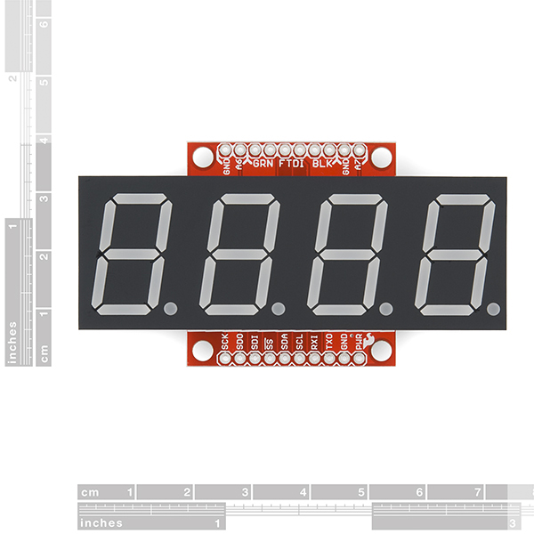
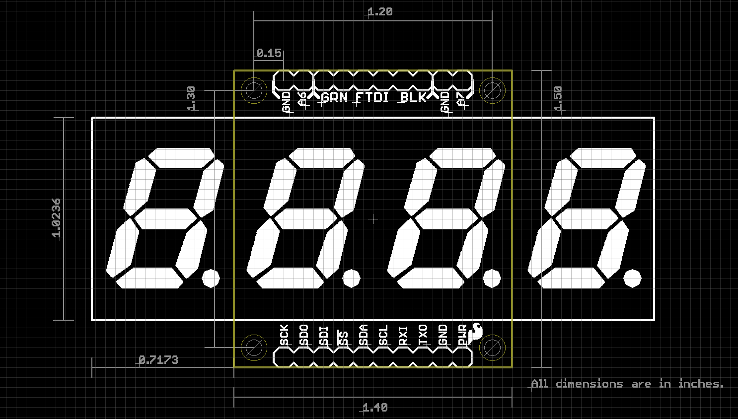
I don't see a mechanical drawing here. What is the character height? What are the XY co-ordinates of the electrical connections and mounting holes? What are the dims of the outline PCB and LED body?
We'll get it fully linked on Monday but I just pushed an image with the dimensions here. We'll also try to get a 3D model created.
Perfect timing! I've been using the smaller version of these, loaded with some custom firmware, as airsoft spawn timers. They work great, but the displays needed to be a little bigger. I've just been asked to build two more timers, I'll be using these displays.
Thanks!
Hah! That's a pretty cool application. These are easy to re-program using an FTDI connection. Let us know how your project goes!