- Home
- Product Categories
- RFID Readers
- RFID Reader ID-20LA (125 kHz)

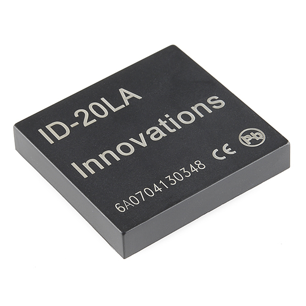
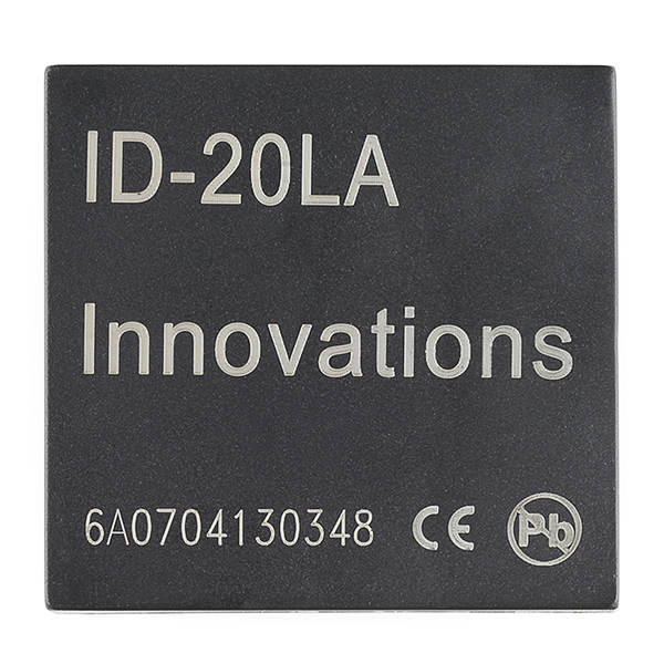
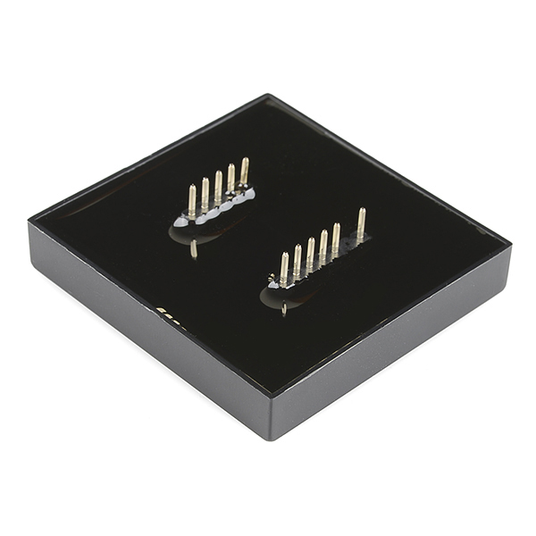
RFID (radio-frequency identification) is the wireless non-contact use of radio-frequency electromagnetic fields, for the purposes of identifying and tracking tags attached to objects. This is the ID-20LA, a very simple to use RFID reader module from ID Innovations. With a built in antenna, the only holdup is the 2mm pin spacing. Power the module, hold up a 125kHz card, and get a serial string output containing the unique ID of the card.
Note: The new ID-20LA is essentially the same as the older ID-20, but has a lower input voltage.
- 2.8 - 5V supply
- 125kHz read frequency
- EM4001 64-bit RFID tag compatible
- 9600bps TTL and RS232 output
- Magnetic stripe emulation output
- Read range of 180mm
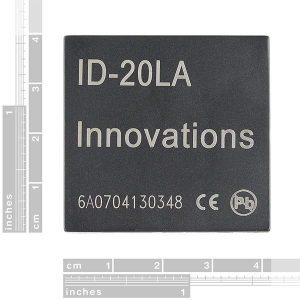
- 38x40x7mm
RFID Reader ID-20LA (125 kHz) Product Help and Resources
SparkFun RFID Starter Kit Hookup Guide
May 5, 2015
Learn the basics of how to get started with the SparkFun RFID Starter Kit.
SparkFun Qwiic RFID-IDXXLA Hookup Guide
March 14, 2019
The Qwiic RFID ID-XXLA is an I2C solution that pairs with the ID-LA modules: ID-3LA, the ID-12LA, or the ID-20LA, and utilizes 125kHz RFID chips. Let's take a look at the hardware used for this tutorial.
Core Skill: Programming
If a board needs code or communicates somehow, you're going to need to know how to program or interface with it. The programming skill is all about communication and code.
Skill Level: Rookie - You will need a better fundamental understand of what code is, and how it works. You will be using beginner-level software and development tools like Arduino. You will be dealing directly with code, but numerous examples and libraries are available. Sensors or shields will communicate with serial or TTL.
See all skill levels
Core Skill: Electrical Prototyping
If it requires power, you need to know how much, what all the pins do, and how to hook it up. You may need to reference datasheets, schematics, and know the ins and outs of electronics.
Skill Level: Competent - You will be required to reference a datasheet or schematic to know how to use a component. Your knowledge of a datasheet will only require basic features like power requirements, pinouts, or communications type. Also, you may need a power supply that?s greater than 12V or more than 1A worth of current.
See all skill levels
Comments
Looking for answers to technical questions?
We welcome your comments and suggestions below. However, if you are looking for solutions to technical questions please see our Technical Assistance page.
Customer Reviews
4.6 out of 5
Based on 8 ratings:
1 of 1 found this helpful:
worked perfect for my application
Size and compact package and easy hook up
1 of 1 found this helpful:
Worked perfectly
I used it with Arduino microcontroller ( mega), and it worked perfectly. the shipping also was fast and very good. Thank you.
No complaints
I'm using this RFID reader in conjunction with a PIC 16F684 and it's working great.
Odd output
The output of this scanner is a little difficult to work with. You are going to get ASCII control characters and hex output. if you want to convert the hex, to the decimal number printed on the card this is what you will have to do: Scanning a card will output something like this "\x020300B9CD5E29/r/n\x03". The data sheet will tell you that the data you want from this is: "0300B9CD5E". What the data sheet doesn't tell you is that you need to scrap the first byte "03". So now you can convert "00B9CD5E" to decimal and get the number printed on the card. With Python that would be int('00B9CD5E',16), this returns 12176734 as expected.
New product for me
I'm new to the RFID field, the reader worked as expected, thenk you! I would like some help to understand the basic functioning of the reader. I'm sending a first request to "technical support" below in this communication. Thanks, Adolfo
works fine
You should link the "Tag In Range" pin to an interrupt pin on your uC. Then you start reading when TIR rise up. Real life reading distance is about 3cm. This device does not repeat the tag. It is emitted only once. Quite sensible to ambiant EM noise, you should "check the checksum" to ensure correct data. It sometimes sends a tag, with a good checksum, that doesn't exists.
To sparkfun team : I used to join VCC to RESET BAR, and GND to FORMAT, it could bea easier to do it with a couple of jumpers on the breakout PCB.
Easy to set up, works perfectly
I am using it with an Adafruit Feather M0 with RFM69HCW packet radio. I was a little concerned about over loading the 3.3 V regulator on the Feather since it's also supplying a radio modem, but haven't noticed any issues. It took only a few minutes from the time I picked the package up from my porch to having the RFID reader wired up and reading tags with a simple Arduino sketch. I notice that the range is greater for cards than than it is for key fobs. The key fobs are detected out to 2 1/2" - 3", while the cards register out to about twice that distance. The Sparkfun wiring guide and the manufacturer's data sheet had all the necessary information needed to properly wire the device to the microcontroller, and to interpret the data sent after the tag is detected.
Solid RFID Module
These modules work great and are one of the few that provide a "RFID in range" output essential for the networked equipment control RFID readers I have design for my makerspace.
To achieve longer range than my previous NFC equipment I ordered the following:
I could read the cards at 8cm maxium ONLY (using a powered USB hub with nothing else connected to it) while the product description claims a 180mm range ! Actual range using matching Sparkfun parts is about half of the claimed range... I was very disappointed !
Later I found this comment from Sparkfun stating that ID-20LA Readers have a 2.75" range maximum using the cards (maximum range is achieved with the cards)
Why not stating that instead in the product description ?
To get a better understanding, I read the datasheet from ID-Innovation and it seems that the design of the USB board is pretty bad to achieve long range: Section 17 advises not to put a copper ground plane nor noisy power supply tracks under the module. The USB board has a wide copper plane and the FTDI USB chip...
Connecting the module to the board using wires (pin 1, 2, 11 and 10) and I could get a little 2 or 3 cm range increase which is significant but still far below expectations.
The datasheet also warns very clearly that power supply requirements are pretty demanding for long range and strongly advises using a regulator based power supply with a voltage ripple of less than 3mV PKPK (recommenging using a ZLCL400 regulator). The USB boards schematics show that the module is fed from the USB 5V without using a regulator !
So I tried powering the module directly from a regulated power supply. Range did not increase both in 3.3V and 5V voltages. Same results when I tried to feed the USB board from that power supply.
I guess this module requires a better power supply to achieve desired range. To be continued !
Tried this with my HID badge used as a key card at work for a fun office project, but cannot read. Anyone know if this will work with HID brand? I noticed that Innovations also sells the ID-12LA-HE which advertises workign with HID, so I suspect there is some reason this one cant, just looking for confirmation.
THanks!
30 March 2018 update... I've used an ID-20 + Arduino as my front door lock since early in 2011... always excellent. Details..
http://sheepdogguides.com/arduino/art3rfid1.htm
Comparison with SEN-11827 would be welcome. That offers only 120mm read distance, and is smaller, and $5 less were what I spotted. Oh... and maybe add the other to the "similar items" list?
Why I receive ID 6A003E43DBCC (or something like that), on the card with ID 0011206400 ?
If anybody is looking to connect this to a Raspberry Pi it's pretty easy. Use one of the 5V pins from the header to power it, along with ground and then just connect the TX pin of the rfid module to the RX pin on the Pi header. I've created a Python module that makes interfacing with the reader quite simple.
Can someone tell me if this reader is able to read a 125 KHz tag (nail type) that uses EM4102 protocol? Thank you in advance
I'd REALLY like to see an antenna or reader with 2-3 foot range. Possible?
Yes, I am looking for one with a better read range as well. I am using the glass capsule RFID and it has to be very close in order to work.
Or... is there somewhere I can buy a bigger inductance coil to somehow attach to the ID-20LA?
Can it read EM4305 tag?
Maybe I am missing it but it would be great if you guys included the Eagle name on the page. Searching ID-20 turns up nothing since you named it ID-12/20. This is a common problem I have had using your library. For example I would have never found LED Tactile button (COM-10442) without someone asking you in the comments section to get the answer TACTILE-PTH-LED-12MM.
Note that in Eagle, you can use the asterisk as a wildcard when searching for parts in the ADD dialog. Searching for ID* will bring back all the parts that start with "ID". Searching for *TACTILE* will bring back all the parts with "TACTILE" anywhere in the name. Sorry that the names are cryptic (as you can see they need to hold a lot of information), but the wildcard trick usually saves the day.
There are still something like 20 TACTILEs in there I would love to be able to just go to the part. I do like that some reference the site number in the description which is also searched. For example entering COM-10063 finds JOYSTICK_MINI. I still maintain it would be great to have the library name on the product page or the productID in the description of the library part.
I know that this won't fit on standard breadboards but I can't seem to find the "breakout board available below." I've searched around on Sparkfun as well and found this: https://www.sparkfun.com/products/retired/8423 which looks like it would do the trick, but it has been discontinued. Someone in the comments recommends this product: https://www.sparkfun.com/products/8272. Is this the solution now?
How does the magnetic stripe emulation output work? Is the output a waveform which could be read using the audio jack of a smartphone (just like the square reader reading magnetic cards)?
This reader is malfunctioning for me. Is there any way I could get it replaced?
In the video he's reading 12 digit codes. Does this chip support 15 digit codes?
The datasheet specifies that it will output 10 ASCII characters that is in hexadecimal, the next two characters are just a checksum and doesn't actually make the code any more unique. So... I guess the answer is no.
Hmm, now that I look more closely, the "15 digit codes" I'm interested in are 15 decimal digits. Unfortunately I think that still works out to about 13 hex digits...
Can you right rfid cards with this.
No, 125 kHz frequency RFID cards are not writeable. Look into MIFARE cards.
So, does this mean that I can use this directly with the raspberry pi?
If you power it directly from the 3.3v (or 5v it looks like?) out of the Raspi, it should work. Skimming through the data sheet I didn't see the current draw, but I doubt it's too much, as long as you're not leaving cards in 'range' for very long.
Since the Pi inputs are 3.3V, you probably should go with 3.3V to power the ID-20LA. At 3.3V, the ID-20LA current draw is about 18 mA both when idle and when a card is in range. At 3.3V the range is reduced to about 5 cm (using a card type RFID tag). At 5V, the current draw is about 27 mA, and the read range is 7 to 8 cm using a card tag.
It looks like the output is open collector.. Does that mean I would be able to power it with 5v for the longer range, and have the output pulled up on a 3.3v GPIO pin on a RPi? I figure if the reader is going to either be open or grounded, then the "high" voltage could depend on the pin it's connected to? Or.. am I missing something?