- Home
- Product Categories
- LED Drivers
- PicoBuck LED Driver

PicoBuck LED Driver
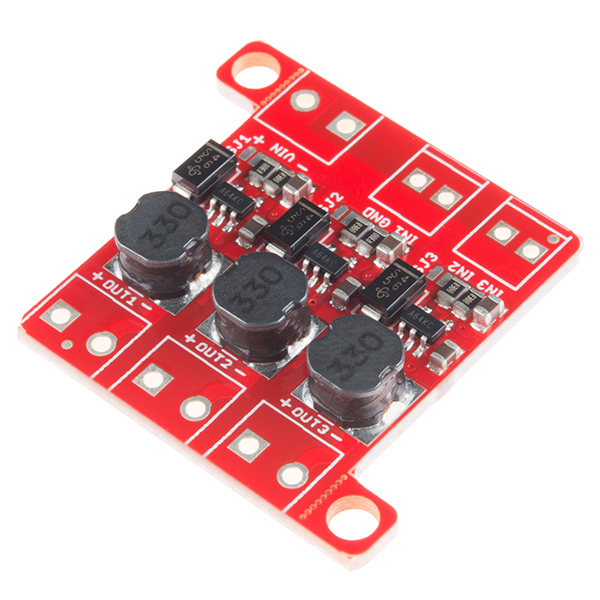
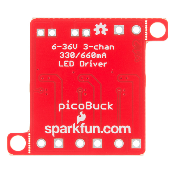
The PicoBuck LED Driver is an economical and easy to use driver that will allow you to control and blend three different LEDs on three different channels. By default, each channel is driven at 330mA; that current can be reduced by either presenting an analog voltage or a PWM signal to the board. Version 12 of the board adds a solderable jumper that can be closed to increase the maximum current to 660mA. The new voltage regulator also increased the voltage rating on the various components on the board, allowing it to be used up to the full 36V rating of the AL8860 part.
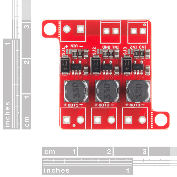
Three signal inputs are provided for dimming control. You can use the PWM signal from an Arduino or your favorite microcontroller to dim each channel individually, or you can tie them all to the same PWM for simultaneous dimming. Dimming can be done by an analog voltage (20%-100% of max current by varying voltage from .5V-2.5V) or by PWM (so long as PWM minimum voltage is less than .4V and maximum voltage is more than 2.4V) for a full 0-100% range. A small jumper is provided for each channel to allow you to increase the drive strength from 330mA to 660mA. Two mounting holes for 4-40 or M3 screws are provided on either side of the board. They are perforated so they can be easily snapped off with a pair of pliers, if a smaller footprint is desired.
Note: If you're going to use screw terminals, this board uses two different sizes. Check the related products for both sizes you'll need.
Note: The PicoBuck LED Driver was made in collaboration with Ethan Zonca. A portion of each sale is given back to him.
PicoBuck LED Driver Product Help and Resources
Touch Potentiometer Hookup Guide
October 22, 2015
Learn how to use the SparkFun Touch Potentiometer to control lighting, volume or other inputs in your daily life.
PicoBuck Hookup Guide v12
February 18, 2016
The PicoBuck board is a high-efficiency three-channel constant-current LED driver.
Core Skill: Soldering
This skill defines how difficult the soldering is on a particular product. It might be a couple simple solder joints, or require special reflow tools.
Skill Level: Rookie - The number of pins increases, and you will have to determine polarity of components and some of the components might be a bit trickier or close together. You might need solder wick or flux.
See all skill levels
Core Skill: Programming
If a board needs code or communicates somehow, you're going to need to know how to program or interface with it. The programming skill is all about communication and code.
Skill Level: Noob - Programming will be limited to basic drag and drop interfaces like ModKit or Scratch. You won't be writing code, but you will still need to understand some basics of interfacing with hardware. If you?re just using a sensor, it's output is analog.
See all skill levels
Core Skill: Electrical Prototyping
If it requires power, you need to know how much, what all the pins do, and how to hook it up. You may need to reference datasheets, schematics, and know the ins and outs of electronics.
Skill Level: Rookie - You may be required to know a bit more about the component, such as orientation, or how to hook it up, in addition to power requirements. You will need to understand polarized components.
See all skill levels
Comments
Looking for answers to technical questions?
We welcome your comments and suggestions below. However, if you are looking for solutions to technical questions please see our Technical Assistance page.
Customer Reviews
4.2 out of 5
Based on 11 ratings:
Exactly what I need
I take old outdoor lighting that ran on AC and convert it to solar powered decorative yard/garden lights. I have a big project and the PicoBuck LED Driver is what I need to control the lighting.
Great
Works well, as advertised. I wish they made the pins spaced by 0.1" instead, it'd be a lot easier to fit in 0.1" protoboards.
Awesome... But Manage Your Expectations!
These things are just peachy! I am building custom dimmable LED lighting for my bedroom, using the COM-13104 3W LED's. SO - first, I bridged the jumpers for the full 660 ma current out, and I tried using just a 10K pot on the input for dimming. It was just OK. Not good control at low levels. So I grabbed a pro-mini (DEV-11113) to do PWM modulation of the input. I even programmed it to give my linear pot a logarithmic taper to give me greater control at the low levels. Much better, but you get definite stepping of intensity as it goes from zero (off) to 1 to 2, etc. Not bad, just a little "steppy". At full intensity, it's like having a handful of small suns. Truly impressive. And surprisingly the LEDs dont get that hot at full power. I used thermally conductive tape (PRT-09771) to fasten the LEDs to an aluminum square tube, and they stay nice and cool.
Very slick little device
Very clean way to drive those high power LEDs (3W). Even when limited to 330mA they are bright enough. Great Application Specific device! A bit pricey though, it really adds up when you use more than a few. Also I think it would be nice to have all the same size screw terminals, since the super small footprint is not needed for my application. Don't get me wrong these are great devices and a perfect solution - the hook-up couldn't be easier.
Works fine
I've got this thing driving strings of LEDs I salvaged from a TV backlight. It just works. Watch out, though. The inductors crack on the top with less crushing force than you might expect. I had two of the three break, not sure how it happened. A little bit of super glue got them back together (mostly affects magnetic shielding, I suspect).
0 of 3 found this helpful:
Burned up my high power leds and eventually burned up the picobuck
I thought I was being extremely careful connecting the picobuck to a Cree XPE2 - RGB High Power LED. Initially I was using an under powered power supply and attempted to use the analog inputs to dim the LEDs to accommodate the 9v battery I was powering it with. The only think I can figure is while trouble shooting I must have input more that 2.5v to the analog dimming input. All three LEDs were fried. While trouble shooting it with different leds one of the chips on the picobuck went up in smoke (with no dimming signal). I gave it two stars because I am sure I am at least partially to blame and I found the Sparkfun user community extremely helpful. Hopefully I will have better luck next time.
Great unit with an even better documentation
Everything about this is great. The documentation covers 99% of everything that you could ever need to know about the unit, and Sparkfun's technical support does its best to address any additional questions regarding the unit.
The only thing that would make this even better is if there was a 1A version commercially available. I understand that you can replace the resistor, but not everyone has that sort of soldering finesse. Soldering a jumper is easy, replacing the resistor is...a bit more of a challenge. I'd even be willing to pay a bit of a premium for that sort of unit.
0 of 3 found this helpful:
Horrible, don't waste your money
Bought this to drive 8 Cree XP-G 5W LEDs; 4 per channel. Started with the default ~300ma drive current and the picco buck could not handle it. It started to heat and burn up. On top of that, one of the channels was deal. I used a 12V 120W power supply, plenty to drive the LEDs. My testing was done with just a single LED and it burned the PiccoBuck. After talking to tech support, they said it will not work with my LED.
What?!?!?! Thanks for the advanced notice, what a useless driver. Got it refunded but lost my shipping charges which account for 30% of the cost.
Trouble-free, works well
This saved me a lot of time and trouble. I was set to build my own drivers that would not have been as good.
Great little driver
These have done great work in several projects, I hope they keep making these for a long time. Never had one fail or burn out, but I'm careful :)
I only wish the pads/through holes were all on 2.5mm spacing so these could be integrated into larger boards with standard headers more easily.
The listing indicates there is a Fritzing part for this item, but it does not show up in the Sparkfun bin (Fritzing v0.9.8). There is a user-made part out there but it's breadboard-only, no PCB profile. Can you confirm if there is in fact a complete Sparkfun-made Fritzing part file for the PicoBuck?
Found it on second deep-dive into github. Could be easier :)
For others: https://github.com/sparkfun/Fritzing_Parts/blob/main/products/13705_sfe_picobuck_led_driver.fzpz
Forgive the noob question but do I still need a current limiting resistor here? If I want to wire 2-3 1W LEDs in series, will 16V work? Having a hard time with my math here :)
Can control (in1\in2\in3) be 3.3v ?
Can i drive 20ma regular 5mm led? (i need 2 high power led and 1 regular)
if so what will be the power dissipation of the sensing resistor (5k from my calculation) ?
"Note: The PicoBuck cannot be used to drive a common anode or common cathode LED or LED string, and the individual channel +/- pads must not be connected to one another."
When testing the positive outputs with a multimeter they all seemed to be tied together. Does this not mean they are common anode?
I am really curious as to why they could not be tied together?
If you look at the schematic, you'll see that there are three independent circuits on this board. When you use a meter to go from positive to positive, you're actually measuring from output 1 +, to VIN through a 0.3ohm resistor, to output 2+ through a 0.3ohm resistor. So they only look like a short.
That's not what the warning is about, though. The warning is about trying to drive a common anode multi-LED strip, and that will fail because the LED with the lowest forward voltage will hog the current until it fails, then the next lowest will hog the current until it fails, and so on. You can't put LEDs in parallel across the output of the PicoBuck.
Interested and planning to purchase this awesome LED Driver. Have been scratching my head attempting to figure out this exact functionality from scratch. Only one thing holding me back at the moment: I would (ideally) like to drive 4 330mA LEDs on a single channel. I see that this board can be adjusted to output 1 A with the correct current sense resister, but I assume any more would be out of the working range of the rest of the parts.
Question: Is there any alternative board that functions identically but at a higher current? I assume that adjusting the current sense resistor to output 1.32 A would compromise the functionality, Do you have a better idea?
You're much better off putting the LEDs in series than in parallel with a constant current driver. Use a higher voltage supply (say, 18V) and stack the LEDs off a PicoBuck.
Have you thought of releasing a 4 channel version for the many high power RGBW/A LEDs out there?
i have several of your 3w leds i would like to get running. is this the driver being used for these or is it the femtobuck. is there a difference between the pico and the femtobuck. pico looks like 3 femtos on one unit. if they are the same it makes more sense dollar wise to buy the pico. are the 3 on the pico isolated so they can be cut apart? seems odd there is such a price difference so just clarifying so i get the correct item. Thank you in advance.
The three units on the PicoBuck are isolated, but cutting them apart probably won't work, because the data and power pins aren't separated on a per-channel basis. You won't get your full 3W out of the LEDs with either of them; depending on the forward voltage, you'll probably only get 1-2W.
Is the current produced by this device purely DC or just 330mA PWM'd to a lower average voltage? Wondering if it can be used to drive LEDs with max. forward current lower than 330mA...
Also: Could you use this device to dim a LED down below its forward current(current needed for the LED to light up at all).
Hi! I have Cree RGBW led chip and cant find driver for it! Can I use that item? thank you
You didnt put a pulldown on the CTRL pin. Even a weak one or just unpopulated pads for resistors woulda been great. My AL8805 board flashes when turned on (till the uC goes low), and will turn on full power if it gets disconnected. 4x10W leds get hot quick.
I think you guys got the price wrong. It seems to be 14950000000000 times too high (before taxes and shipping).
~~Can't view the schematic, it keeps returning an Error 403.~~ Fixed now.
try this one https://cdn.sparkfun.com/assets/learn_tutorials/4/4/3/PicoBuckV12Schematic.pdf
So I literally purchased the previous version to this product last week and was wondering how to boost the current to above 330mA.... sigh.
It's not a terribly difficult modification to procure another SMD resistor (Digi-Key is a good source) and either replace the one on the board, or stack the new one on top of the existing one. The formula for the resistor size is on the schematic.
Thanks i did just that! Hardest part was the soldering since i never did SMD but I did it.