- Home
- Product Categories
- Arduino Shields
- LCD Button Shield

LCD Button Shield
Do you need an easy to use interface for your LCD screen? The LCD Button Shield just might be your answer! Moving through menus and making selections straight from one stand-alone shield attached to your Arduino is a great way to cut down on your tower of shields.
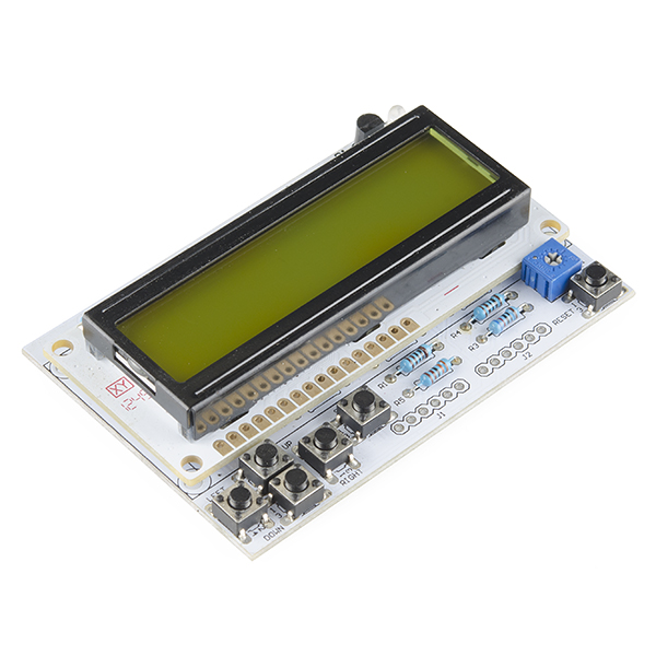
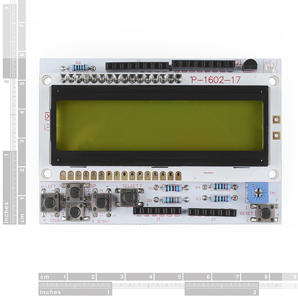
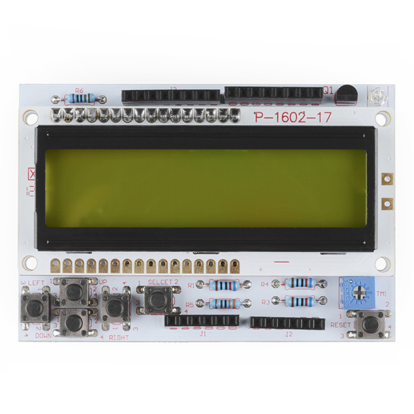
The LCD Button Shield consists of a 16x2, black character, green backlight LCD with a keypad consisting of 5 keys — select, up, right, down and left. To save the digital IO pins, the keypad interface uses only one ADC channel. The key value is read through a 5 stage voltage divider.
Check the link below for example code, schematics, and additional information.
Note: Headers are included but not soldered.
LCD Button Shield Product Help and Resources
Core Skill: Soldering
This skill defines how difficult the soldering is on a particular product. It might be a couple simple solder joints, or require special reflow tools.
Skill Level: Noob - Some basic soldering is required, but it is limited to a just a few pins, basic through-hole soldering, and couple (if any) polarized components. A basic soldering iron is all you should need.
See all skill levels
Core Skill: Programming
If a board needs code or communicates somehow, you're going to need to know how to program or interface with it. The programming skill is all about communication and code.
Skill Level: Rookie - You will need a better fundamental understand of what code is, and how it works. You will be using beginner-level software and development tools like Arduino. You will be dealing directly with code, but numerous examples and libraries are available. Sensors or shields will communicate with serial or TTL.
See all skill levels
Core Skill: Electrical Prototyping
If it requires power, you need to know how much, what all the pins do, and how to hook it up. You may need to reference datasheets, schematics, and know the ins and outs of electronics.
Skill Level: Rookie - You may be required to know a bit more about the component, such as orientation, or how to hook it up, in addition to power requirements. You will need to understand polarized components.
See all skill levels
Comments
Looking for answers to technical questions?
We welcome your comments and suggestions below. However, if you are looking for solutions to technical questions please see our Technical Assistance page.
Customer Reviews
5 out of 5
Based on 2 ratings:
1 of 1 found this helpful:
Lower cost alternative to the SainSmart LCD Keyboard
Functionally, I can see little significant difference between this and the more expensive SainSmart unit. Some differences are that the SainSmart item has additional through hole connections available, whereas this one does not. But I installed long pin header sockets, that allowed access to these connections, as well as plug into an arduino uno, or any microcontroller board with the same footprint (e.g., the 'Olimexino' 5510). Another is the placement of the Reset button, which was not grouped with the other buttons; but is set at the lower right corner... This was not significant for my application, and even made for easier access.
As for software compatibility, it appears to be 100%. For the price, I think it's a great alternative, and plan to purchase this again for other projects where it is needed.
Beautifully Designed
Work great for the project I am making. Easy to use, code examples were helpful. The buttons adds to the product nicely. The variable brightness of the screen makes it easy to see the characters. Overall, a well rounded product.
I think a terrific 'companion' to this product would be a nice plastic case. Something that brings the buttons to the outside of the case and maybe an option for either 'clear' or black.
Grab 5 of these
I tried this because of this comment and it did not go well. The PCB that the switches are mounted on has really thorough vias that hold a lot of solder, and the solder they used melts to a paste that doesn't want to be removed. There's also solder on the top and the bottom of the board.
The datasheet does claim it's panel-mount ready but the real hitch for most hobbyists, of course, is manufacturing membranes for the buttons or designing a knob for the pot. That being said, as everything on this shield appears to be PTH, it would be fairly easy to remove the buttons, bring them to the case and use either jumper wires or a custom cable (perhaps after creating a small custom board for the buttons). This approach also enables replacement of the provided buttons with ones that better suit the needs of a build, for example, SFE's concave panel-mount buttons or their 5-way Tactile Switch. I would also imagine that the screen itself can be detached and replaced with any equivalent 16x2 that uses the HD44780 interface if a different colour is desired or a different orientation to the case is required. I believe all of SFE's 5V screens of that size would therefore work.
Those things are probably all true, but if you are going to go through that much work why buy the shield in the first place, just get a screen and some buttons. Seriously though this is the issue with pretty much all shields, its someone else building a breakout board for you with the features they think will work best on the pins they want. If you want slightly different features or pins sometimes its easier to just build your own board.
Exactly. I purchased this yesterday so I can have just my Redboard and shield on my desk, instead of a rats-nest of jumper wires going everywhere, and so far I really like this thing. Once I get everything ironed out, I plan to machine my own case with bigger buttons and use a different LCD for my project. Only gripe is the overly bright power LED...I'm going to get some heat-shrink on there before I go blind.
I had to compare your product with a similar offering from Adafruit http://www.adafruit.com/products/772 Your's is about $5 cheaper, but the Adafruit only needs TWO pins to do everything since they include a built in I2C I/O expander to do the dirty work. Both ways work, and your's might be a bit easier to program as you don't have to mess with the I2C driver library. In anycase it's nice to have a choice!
I use the adafruit one and I think sparkfun could do the same thing very easily
Adafruit's I2C version uses a modified LCD library. From the developer's perspective there is no change except the initialization of the LCD. You can also buy the Adafruit LCD backpack for about $11 which you can hook up your own LCD instead of the standard 16x2 one.
Will this work with the Intel Edison?
Nevermind, it should.
When they say "Check the link below for example code..." they mean this link. http://linksprite.com/wiki/index.php5?title=16_X_2_LCD_Keypad_Shield_for_Arduino
The circuit with the 5 push-buttons can easily be replicated and used instead of the onboard switches...see the schematic in the section of the product page entitled "reading the buttons". All you need to do is to wire up the 5 discrete push buttons and 5 resistors as shown in the schematic and they can be used instead of the on-board buttons without any modifications (the existing switches can be left alone).
hi everyone ,i have an arduino + lcd keypad and i want to put a function in a case menu but i dont know how .th function must count how many times i push a button in a period of time.i use pin 2 and 3 for buton.if somebody can help me with the cod.
my menu cod is this:
include <LiquidCrystal.h>
// Initialize the library with the numbers of the interface pins LiquidCrystal lcd(8, 9, 4, 5, 6, 7);
//States for the menu. int currentMenuItem = 0; int lastState = 0;
void setup() { //Set the characters and column numbers. lcd.begin(16, 2); //Print default title. clearPrintTitle(); }
void loop() { //Call the main menu. mainMenu(); }
void mainMenu() { //State = 0 every loop cycle. int state = 0; //Refresh the button pressed. int x = analogRead (0); //Set the Row 0, Col 0 position. lcd.setCursor(0,0);
//Check analog values from LCD Keypad Shield if (x < 100) { //Right } else if (x < 200) { //Up state = 1; } else if (x < 400){ //Down state = 2; } else if (x < 600){ //Left } else if (x < 800){ //Select state = 3; }
//If we are out of bounds on th menu then reset it. if (currentMenuItem < 0 || currentMenuItem > 4) { currentMenuItem = 0; }
//If we have changed Index, saves re-draws. if (state != lastState) { if (state == 1) { //If Up currentMenuItem = currentMenuItem - 1; displayMenu(currentMenuItem); } else if (state == 2) { //If Down currentMenuItem = currentMenuItem + 1;
displayMenu(currentMenuItem); } else if (state == 3) { //If Selected selectMenu(currentMenuItem); } //Save the last State to compare. lastState = state; } //Small delay delay(5); }
//Display Menu Option based on Index. void displayMenu(int x) { switch (x) { case 1: clearPrintTitle(); lcd.print ("->TESTARE BATRANI"); break; case 2: clearPrintTitle(); lcd.print ("->TESTARE TINERI"); break; case 3: clearPrintTitle(); lcd.print ("->TESTARE COPII"); break; } }
//Print a basic header on Row 1. void clearPrintTitle() { lcd.clear(); lcd.setCursor(0,0); lcd.print("MENU TESTER"); lcd.setCursor(0,1); }
//Show the selection on Screen. void selectMenu(int x) { switch (x) { case 1: clearPrintTitle(); lcd.print ("Selectat TEST BATRANI"); //Call the function that belongs to Option 1 break; case 2: clearPrintTitle(); lcd.print ("Selectat TEST TINERI"); //Call the function that belongs to Option 2 break; case 3: clearPrintTitle(); lcd.print ("Selectat TEST COPII"); //Call the function that belongs to Option 3 break; } }
is this shield Leonardo compatible? I plugged mine in using the headers, and on top (no pun intended) of the fit being extremely loose (I have to press with my fingers to make it engage) I only get a row of black boxes on top and nothing at the bottom. My IDE has liquid crystal.
Hello,
I just received my LCD Button Shield and I am having trouble getting it to display. When I plug it directly into the arduino the red LED lights up and on the display is a row of black boxes. When I try and upload any of the sketches form the LiquidCrystal library I get no change in the display. Also, when I hook it up to my 2nd arduino board it doesnt light up at all unless I jiggle it around a little and then it flickers. I feel like the header pins don't make that well of contact? Can anyone give me some insight into what I am doing wrong here or if I have a defective LCD?
-Thanks
I used PRT-10158 rather than PRT-11417. Now I am out! Where is my shopping cart?
http://linksprite.com/wiki/index.php5?title=16_X_2_LCD_Keypad_Shield_for_Arduino
r1.0.5 and r1.5.5 throw ~30 errors when including LCD4Bit_mod
I have emailed linksprite tech support. hopefully they have a resolution.
Edit: in less than 10 minutes, they had an automated ticket generated. pleasant surprise
Edit: So far, they have re-affirmed that it compiles in Arduino 0021! not looking good.
They released a new library for 1.05-1.5.6 https://s3.amazonaws.com/linksprite/Shields/16X2+LCD+Keypad+shield/LCD4Bit_mod(for+Arduino+1.0.5-r2).zip
It does compile without error in 1.05 and 1.5.5.
Is there any possibility of using this shield with your OLED display LCD-11987, without too much grief?
The Shield is nice, but comes with the stackable headers already soldered! I would have preferred the Note displayed about it to be respected: Note: Headers are included but not soldered. grrr!
I double-checked our stock and the headers are not presoldered onto the boards. Shoot techsupport@sparkfun an email and they should be able to help you out with this if it actually affects your project. I'm not really sure how you managed to get an assembled one, unless it was a mistake by the manufacturer. We don't assemble or check these in-house, which is how it was missed. Sorry about that!
Actually the initial order we got came with headers, the new order does not have them and we are in the process of changing things over. So anything order up until a couple of weeks ago had headers, what's in stock now does not.
Thanks for the reply Toni, finally not a big deal, I can heat my iron unsolder and replace with straight and right angle pins, no luck with headers, luck in love ;-)
This uses a lot of pins! A better version would be able to select the interface, UART, I2C or SPI... This one does that all, has a color backlight, and uses an ARM Cortex for more horsepower : http://www.patternagents.com/projects/Videre.html
Cannot get the pixels to go away no matter what power source I use,could use some suggestions.
I got one of these and had problems because I was using and Chipkit MAX 32. The reason for this is the the buttons are made to be read from a 5v ADC source. On the Arduino Due, Chipket Uno 32, and Chipkit MAX 32 operate on 3.3v. So what is happening is any voltage read from the ADC over 3.3v is read as 3.3v. What I did to fix the problem is change the resistor at R6 from a 2k to a 3.9k. This is a simple fix and the buttons work great now. The LCD Button Shield is a great product and hope if you are looking at any shields that are made for the Arduino UNO that you make sure it does not require the 5v ADC reading.
Been using this exact product for years already: http://www.jameco.com/webapp/wcs/stores/servlet/Product_10001_10001_2144411_-1
What would happen when 2 buttons are pressed at once? Would you get a weird analog reading?
The button that is hooked up to the lowest resistance is what gets reported. If you check out the schematic, you'll see that all the switches are connected directly on the right side.
So let's say you press the Left button at first, which causes the voltage divider to end up running through the 330 Ohm, 620 Ohm and 1 kOhm resistors in series, or 1950 Ohm total.
Now let's say you also press the Select button. At first you might think this adds the 3.3 kOhm resistor into the mix. However, because the switches are all connected directly on the other side, you've basically got another resistor of 0 (zero) Ohm in parallel to it, making the combined resistance pretty much 0 Ohm, and you're left with the 1950 Ohm.
If instead you add the Down button, the direct connection between the left and the down buttons ends up in parallel to the 1 kOhm resistor, removing that, and thus leaving you only with the 330 Ohm and 620 Ohm resistors, same as if you had only pressed the Down button.
If instead of the direct connections there had been further resistors (carefully selected) on the right side of the switches, then it could have been made to detect multiple buttons being pressed at once as well, though the error margin in the analog read would also get to be much lower. Fun exercise: figure out the optimal resistor values (let's stick to the E12 range) to use for such a situation. Aspirin's on me :)
Is this shield compatible with the official Arduino Wi-Fi shield? I'm not sure if they'll work fine together because of pins 10 and 7... (Arduino UNO)
I wouldn't bother. Arduino wifi shield has an antenna made of copper trace on the board, which is pretty weak. I don't want to put anything above it. To answer your question, no pin 7 is used on both shields. I would do a serial lcd with keypad instead. The one that Liudr makes is the best ;) This shield is simply a recast of sansmart or other lcd shields that have been around for a long time. Nothing interesting. My own shield comes with lots of libraries and full project codes btw. Interestingly sparkfun is not interested in selling any of my designs. Good for me.
I was curious what would happen if you held down more than one button simultaneously. Looking at the schematic, it looks like it would just read as whichever button has the lowest voltage, no invalid in-between state or current shoot-through or anything. Very interesting design!
The front side female headers would make it tough to build a front panel around this shield. Not to mention any shield on top would cover most of the LCD and/or buttons.
Get an LCD module for front panel stuff. This shield or most other lcd shields are NOT designed to be mounted on a front panel.
It's great that they don't interfere with panel mounting, but is there even any point to putting stackable headers on an LCD shield?
Putting in test leads or linking to BOBs from above springs to mind. But point taken.
Interfacing a bunch of buttons to 1 analog in pin by using a voltage divider to assign a analog value to each button... Why the heck didn't i think of that!!! Its ingenious and could solve my pin shortage in my current project. TO THE BREADBOARD!!!!
I love reading new products and schematics, never know when you may find a simple yet effetive solution or just plain inspiration for a experiment.
Just be careful about noise if you're multiplexing a bunch of values and are in a noisy environment (although 5 values across 0-5V should be pretty damn noise tolerant :p). Your debouncing might also be a little weird and you loose the ability to do interrupts, but hey, small price to pay for 1-wire compatibility. The concept is pretty much the same as how RC controllers do it (except obviously they use PWM instead of raw analog) for multi-position switches. I'm impressed Sparkfun, especially for the price, with this board. Might have to pick up a couple at some point just to mess around with.