- Home
- Product Categories
- Power Connectors
- DC Barrel Power Jack/Connector

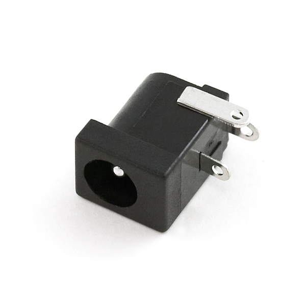
DC power jack/connector. This is a common barrel-type power jack for DC wall supplies. These are compatible with our DC wall supplies and have a 5.5mm jack, with a 2.1mm center pole diameter.
DC Barrel Power Jack/Connector Product Help and Resources
Buck Regulator Hookup Guide
August 5, 2021
Get started with SparkFun's newest Buck Regulator Boards - the BabyBuck and the Buck!
Connector Basics
January 18, 2013
Connectors are a major source of confusion for people just beginning electronics. The number of different options, terms, and names of connectors can make selecting one, or finding the one you need, daunting. This article will help you get a jump on the world of connectors.
Pinout
For a quick reference, the image below shows pinout.
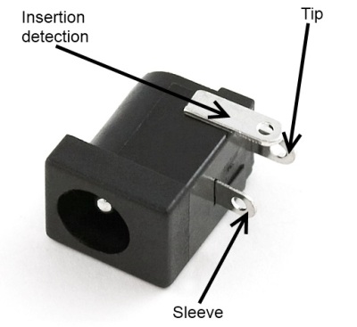
Image from the Connector Basics: Power Connector Tutorial
To connect to the DC barrel jack adapter using a center positive power supply, the pinout of the barrel jack adapter is:
Barrel Jack = Pinout
Center "Tip"= Vcc, pin opposite of barrel jack input that is usually your "**+**" input voltage
Shunt = side pin opens when a plug is inserted into the jack
Sleeve = GND, pin closest to the barrel jack's input and it is usually "**-**"  ground
Make sure to test your circuit's connection with a multimeter set to measure before powering up.
Resources and Going Further
For more information, check out this forum post in the Electronics Stack Exchange [ https://electronics.stackexchange.com/questions/141897/dc-power-supply-jack-connector-pinout ].
Core Skill: Electrical Prototyping
If it requires power, you need to know how much, what all the pins do, and how to hook it up. You may need to reference datasheets, schematics, and know the ins and outs of electronics.
Skill Level: Rookie - You may be required to know a bit more about the component, such as orientation, or how to hook it up, in addition to power requirements. You will need to understand polarized components.
See all skill levels
Comments
Looking for answers to technical questions?
We welcome your comments and suggestions below. However, if you are looking for solutions to technical questions please see our Technical Assistance page.
Customer Reviews
3 out of 5
Based on 2 ratings:
4 of 4 found this helpful:
Not making contact
The ground contactor is not connecting with the barrel on the unit I purchased. I hope it's just a fluke, so I'm buying another one. I've tried pushing the tab back and forth and up and down with no luck.
It also would be nicer if these were regular through-hole pins instead of the tabs. The layout for this part on sparkfun's eagle library just has round holes that these tabs don't fit through.
New design? As of the end of 2013, you want product 10811 instead.
By the datasheets product 10811 withstands higher voltages and currents, and by the product description it has the additional capability to be used on a breadboard prototype before you solder it all down. As annoying as it may be to post a product discouragement here, this here is a distracting product: it does less of the same thing as 10811 at a higher cost. The newer product (this one is 119 - from much earlier in Sparkfun's history) appears significantly better.
I'm pretty happy that Sparkfun chose to add the better one when they found it. Thanks! Now, retire this one, so we don't have the Mouser/Digikey/Farnell/etc "How many datasheets do I have to read to pick a jack/resistor/LED/bananaphone/transistor/wire?" problem. That's a yak I don't want to shave.
But! - If you already have a pcb, and it need this footprint, then this would still be the right one.
If I missed any other reasons why you'd prefer this over the other one, please correct me! People buying the wrong product for what they need is sad. : (
If you need RoHS compliance, the breadboard friendly version doesn't seem to cut it. For most of us, this isn't an issue, however it's something to keep in mind.
If using this with a standard center-positive 5.5x2.1mm barrel connector: The leg in the center of the plastic body is the positive lead, while the other two (on the outer edges of the plastic body) are both connected to one another and are the negative leads.
Huh? The V+ is the Rear leg (not the center leg). This will matter if doing a PCB. The center and side leg are normally tied together to GND.
so can we clear this once and for all--which pins stand for what? the datasheet is complete crap imo
The back leg is the center pole.
The leg in the middle of the connector is tied to the outer barrel.
The leg on the side is a switch. It is tied to the barrel when there is nothing plugged into the jack and it is open when something is plugged in.
V+ and GND depend on if the power adapter you're using is center positive or center negative. Sparkfun's adapters are center positive.
I'd consider eating my shorts if sparkfun sold one of these barrel jacks that's compatible with a breadboard.
http://www.sparkfun.com/products/10811 Video or it didn't happen! :)
yeah, or pics. either one.
Heck, I'd even consider eating your shorts if they'd do that.
Deliver?
Anyone have a lead on a breakout board for this guy? I've got some copper clad but I figured I'd see if something was pre-made first.
The SparkFun EAGLE library has this part; however, I'm a bit confused how to interpret the schematic diagram. The diagram has a filled rectangle in the upper left with a thin line extending out from the rectangle to the right. Below that are two more lines extending to the right. At the very bottom is a + symbol. Which ports provide the positive and negative power supply?
The rectangle is the center (pin), the middle line is the switch, the bottom line is the barrel. The '+ symbol' is just the registration mark for the schematic symbol, not a label :)
See AndrewParnell's comment for information on which physical pin is what and a pointer on polarity.
Newark has a pretty good deal on a nearly identical part: Part: 08WX2563
It's a 10-pack for $5.24. So it's still cheaper to pick up a couple here on sparkfun unless you need them in bulk.
How are you supposed to mount a jack like this in a case?
I assume you're supposed to solder cables directly to the through-hole lugs, since they don't have the solder profiles like this one.
How, then do you hold the jack in place?
Thanks to anyone who can enlighten me.
These are intended to be board-mounted (i.e. directly soldered to a PCB), just like the one you linked to. You would design your board/case mounting so that this lines up with a cut-out (where the case slides over the jack) or a window (where the jack's hole lines up with another hole).
I'm partial to panel mount jacks myself - much more flexible in terms of mounting options, but not really fit for mass-produced consumer products.. if only because you don't want somebody unscrewing the locking ring and then have the jack disappear into the body, wreaking havoc ;)
I think there is a typo in the description: according to digikey, this is a 5.5mm jack, not 5mm.
Why are there two ground pins? It fits in my breadboard but it is at an angle and only one ground pin is in, the other is not, is that dangerous or can i work with it?
You might want to get the breadboard version of this jack...
does this fit on the 4 inch protoboard
also heres the link to the product your looking for ignore my other post. http://www.sparkfun.com/products/10811 pleasure shareing ingenuity withg you.
no it dosent it's diamater is a little large just solder some wires to the pins and then your all set. ps hope this helps good luck.
As usual, make sure you read the datasheet, even on something this easy. Don't be like me! :) Contacts 2 and 3 aren't the same - sure they are connected when you put your VOM on them, but that's only until the barrel plug is inserted - then a contact opens and the side pin is disconnected.
I guess this is so you can have it autoselect multiple power sources, but if you just need power, be sure to use the rear (tip) and bottom (ring) pins, not the side!
I used a similar technique as nike to mount this to a pref board. I filed down the edges of the bottom pins on each side. I also left the side tab full size, but bent it sideways so a wire could be run through it and the pref board. I then soldered the wire on each side to help hold the connector in place as the much smaller center pins, after being reduced in size don't provide much strength.
The data sheet clearly says that the center pin is 2.0mm in diameter. Barrel jack dimensions are confusing.
I soldered some male header pins to this and put it in a breadboard.
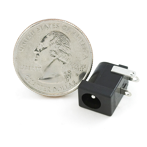
FYI, The scale reference in the pictures is hilariously wrong.
How easily will one of these fit into a protoboard with 0.1" spacing?
Great catch on the scale, we'll get that fixed!
Unfortunately these won't fit well on a breadboard - the pins aren't on a 0.1" grid and are too large for the breadboard holes anyway. I've soldered short wires on these for exactly this purpose, though it's a little too easy to move the power cord and pull it out of the board.
I have found a simple solution to make these fit easily into a .1" proto board. I clipped of the bottom lead as flush as possible, then bend the other 2 leads 90 degrees so the holes are facing downward, then i put a small length of solid wire in and soldered it going straight down. if you bend them a little they will fit nicely, and flush, into a power rail, or onto a pcb. A bit of hot glue under it will make a nice solid fit on a pcb.
Will this work on the Arduino Pro board?
Can and will.
Why do you only sell the jack, but not the plug?
https://www.sparkfun.com/products/11476
They do. Do a search for "power" and you'll see a whole bunch of wall warts at various voltages.
Ummm, I think they mean a male version of this.
It's hard to find male barrel jack connectors. They do sell a screw terminal version of the male jack, and ones that adapt to a JST and 9-volt battery, but you will have a hard time finding any other type. I assume this is because companies don't want consumers making their own power plugs.