- Home
- Product Categories
- Button
- Metal Pushbutton - Momentary (16mm, Red)

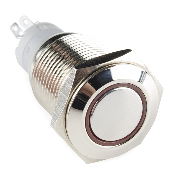
Metal Pushbutton - Momentary (16mm, Red)
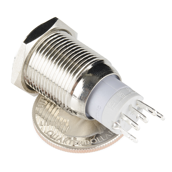
This is a perfect choice if you are in need of a heavy duty push button! These metal push buttons are a very tough, small, panel-mount momentary switch with an illuminated red LED ring. It is a SPDT with 16mm threading and 1mm pitch. This button is perfect for basic On/Off functions. Overall length (including leads) is 1.5" and has small solder lugs for connection. These momentary buttons are rated up to 3A and 250VAC while the LED is rated for 5-12V.
Note: The images for this button show an LED voltage rating of 5V. We have verified that the voltage range for the the LED to be 5-12V. We are currently communicating with our supplier for new documentation. Trust the branding on the button to verify your voltage requirement.
- Stainless Steel Body
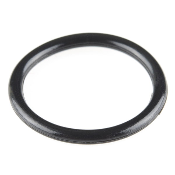
- IP65 Waterproof Rating
- Momentary Operation Type
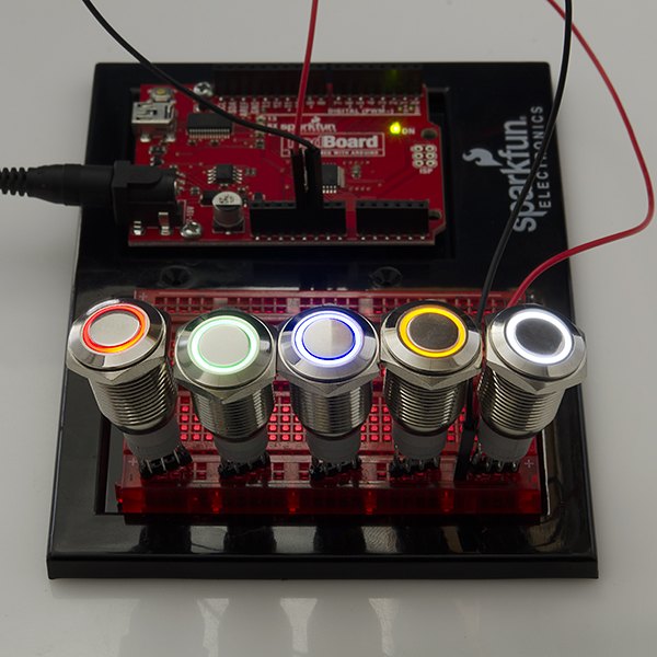
- Red LED Ring
Metal Pushbutton - Momentary (16mm, Red) Product Help and Resources
Wireless Audio Bluetooth Adapter w/ BC127
December 14, 2017
Build a custom wireless audio Bluetooth adapter using BlueCreation's BC127 and add it to your old speaker system!
Wireless Timing Project
September 29, 2022
Time for racing, let's make a wireless timing device using ESP32 wireless communication.
Pinout
The pushbuttons (like the momentary https://www.sparkfun.com/products/11966 or latching https://www.sparkfun.com/products/11971 ) have an indication of the pinout of the buttons on the side of the plastic molding. One way to test the switch is to use a multimeter turned to the continuity setting. Here are what the pins (not in any particular order associated with the pushbutton's spades):
+ = LED Anode
- = LED Cathode
C = "Common Ground"
NC = Normally Closed
NO = Normally Open
One way to light the LED on the metal push button would require you to wire it so that when you press down on the button, the led would light up. You would need 5V to light the LED ring. It can be lit up with a smaller voltage but the LED won't light up as bright.
To connect the battery to the button so that it only lights when the switch is pressed down (momentary or latched), you would connect 5V to the "+" pin on the switch. This is assuming that your system is using the same voltage source that is 5V. Then from the "+" pin, you would wire it to the normally open (NO) pin.
Another wire would be connected from the "-" pin to the C pin. The C pin would essentially be connected to your ground. So as you press down on the button, it would flip the switch and complete the circuit from the normally closed (NC) pin to normally open (NO) pin while lighting the LED ring at the same time. It might be a good idea to use a current limiting resistor (like standard 330Ohm resistor) if you are using 5V directly from your power supply. The LED won't be as bright but you also wouldn't be reducing the life of the LED. I am not sure of the electrical characteristics of the LED that is in the pushbutton.
Core Skill: DIY
Whether it's for assembling a kit, hacking an enclosure, or creating your own parts; the DIY skill is all about knowing how to use tools and the techniques associated with them.
Skill Level: Noob - Basic assembly is required. You may need to provide your own basic tools like a screwdriver, hammer or scissors. Power tools or custom parts are not required. Instructions will be included and easy to follow. Sewing may be required, but only with included patterns.
See all skill levels
Core Skill: Electrical Prototyping
If it requires power, you need to know how much, what all the pins do, and how to hook it up. You may need to reference datasheets, schematics, and know the ins and outs of electronics.
Skill Level: Competent - You will be required to reference a datasheet or schematic to know how to use a component. Your knowledge of a datasheet will only require basic features like power requirements, pinouts, or communications type. Also, you may need a power supply that?s greater than 12V or more than 1A worth of current.
See all skill levels
Comments
Looking for answers to technical questions?
We welcome your comments and suggestions below. However, if you are looking for solutions to technical questions please see our Technical Assistance page.
Customer Reviews
4.1 out of 5
Based on 8 ratings:
1 of 1 found this helpful:
Clean look
Worked as it should. Check your depth, this thing is longer than I expected. I almost didn't have enough room for it.
3 of 3 found this helpful:
Pulls 33-36 mA at 12 V
I've not tested these yet, but they seem well-built.
1) For those who wonder about the pinout as I did before receiving one, look at a bottom view photo or 3D rendering and orient it such that the pins resemble a smile rather than a frown. Starting from the left and going CCW:
LED +
N.C.
N.O.
Common
LED -
2) I would not be comfortable connecting these to more than about 9 VDC without adding a series resistor. My testing shows that the red LED pulls 36 mA and the green LED pulls 33 mA at 12 VDC, both of which are higher than small LEDs normally prefer. FWIW, I also determined that the internal red LED has a Vfwd of 1.8 V and the green Vfwd = 2.4 V, approximately, and it seems that each has a 290 ohm series resistor within the pushbutton housing. I plan to connect these LEDs to a 24 VDC circuit with the addition of an external 1 kilohm series resistor to limit the current to about 16 mA.
Good button
Good button, but for $6.00 I'd expect that the data sheet included a pin out.
Sorry about that. We didn't bother putting the pinout on the data sheet since it's already printed on the switch itself. If you look in the "Product Help and Resources" section above and click on "Tech tips" we have a description of what the pins do.
Nice button
The action is comfortable, it clicks around 1.5mm and bottoms out at 3mm. The opening is just big enough for an intentionally-placed finger. The red ring is evenly lit and comfortably bright at 5V.
works well, but dodgy to solder
These metal pushbutton switches (all colors) function well. The pin-out is a little hard to track down (it's marked with barely legible icons on the switch body, and can be found in the comments). My main objection is that, when I solder a lead to one of the terminals, the terminal shifts around in the plastic body. I was able to reduce this by using heat sink tweezers at the base of the pin, but I have to wonder how much rework this switch can take before it loses some internal continuity.
Low profile, bright and easy to see and no need for external resistors for the LED
Very nice button
Very nice button. Well built and heavy construction. I am using 5 of them in a target control build (3 red and 2 green). At this time I am confident they will perform well in the field. Thanks SparkFun a perfect match for my project.
What is the easiest way to solder wires onto these? I have the Hakko soldering station sold by SparkFun and stranded 22awg wire. When I try, the wires either tough the other terminals or the solder bridges the gap. Is there any chance that SparkFun could offer a breakout board with headers?
Does anyone have either: a) An Eagle library with these in them, so I can make a mounting board b) The size of the terminal, so I can purchase a quick connect-disconnect or crimp shroud?
I love these things, and we are using them by the dozen, but I need a better way of connecting 9 at a time, instead of looping wires & hand-soldering!!
(PORTED to TECH TIPS TAB)
-------------------- Tech Support Tips/Troubleshooting/Common Issues --------------------
Pinout
The pushbuttons (like the momentary https://www.sparkfun.com/products/11966 or latching https://www.sparkfun.com/products/11971 ) have an indication of the pinout of the buttons on the side of the plastic molding. One way to test the switch is to use a multimeter turned to the continuity setting. Here are what the pins (not in any particular order associated with the pushbutton's spades):
One way to light the LED on the metal push button would require you to wire it so that when you press down on the button, the led would light up. You would need 5V to light the LED ring. It can be lit up with a smaller voltage but the LED won't light up as bright.
To connect the battery to the button so that it only lights when the switch is pressed down (momentary or latched), you would connect 5V to the "+" pin on the switch. This is assuming that your system is using the same voltage source that is 5V. Then from the "+" pin, you would wire it to the normally open (NO) pin.
Another wire would be connected from the "-" pin to the C pin. The C pin would essentially be connected to your ground. So as you press down on the button, it would flip the switch and complete the circuit from the normally closed (NC) pin to normally open (NO) pin while lighting the LED ring at the same time. It might be a good idea to use a current limiting resistor (like standard 330Ohm resistor) if you are using 5V directly from your power supply. The LED won't be as bright but you also wouldn't be reducing the life of the LED. I am not sure of the electrical characteristics of the LED that is in the pushbutton.
There appears to be a resistor in the switch already!
I was planning to use this switch to interrupt a 12V 6A power supply running a series of LED light strips on my cabinets. Is the amperage provided by the power supply too high for this switch?
Any help in using an arduino to read the switch? I'm trying to read the momentary switch on a digital pin.
What is the LED forward voltage or forward current? Does this have a current limiting resistor already installed? If so how much power does the LED consume? I ask because of a off grid system that I am working on and need things to be very power efficient.
On a bench supply, these red ones draw about 17mA at 5V.
What board are you hooking these into in the photo above?
Are these difficult to press if you have big fingers? I've tried a similar looking button in the past and I had to push it with my pinky, and it had sharp edges which hurt my lateral nail fold.
These look great - I'm going to have to order some to play around with... How much travel do these have, and do the have a tactile click when they engage?
It would be great if you made an RGB LED version of this.
Also, it would be very cool if the metal button cap had an electrical connection so you could use a capacitive switching circuit to get two levels of switching in a single switch (kind of like cameras that use a light press to focus, and a full press for the shutter).
they do have a click. they actually have a good amount of travel, so it's hard to accidentally press them. you certainly have to push them in a bit.
so, the LEDs in these are electrically connected to the buttons how exactly? are they always on? or do they have pins that are independent of the button that can be wired to a micro-controller?
there are 5 pins on the bottom. three are for the switch and two are for the LED. it works separately. apply power, it lights up, take away power, it turns off (and gets upset at you). the switch part is independent.
If that's the case, please correct the features for the locking versions which says '(1NO1NC/2NO2NC)'. The voltage drop on the LEDs would be nice, too, in case 5V isn't handy — a regulator seems a bit much for one LED. Thanks.
okay! that's what i was hoping for! i'll be getting a couple!
You stocked them! Now I'm gonna have to order one or ten!
or twenty, why not?