- Home
- Product Categories
- 3-axis
- SparkFun Triple-Axis Digital-Output Gyro Breakout - ITG-3200

SparkFun Triple-Axis Digital-Output Gyro Breakout - ITG-3200
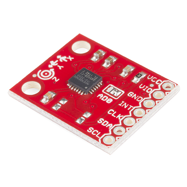
This is a breakout board for InvenSense's ITG-3200, a groundbreaking triple-axis, digital output MEMS gyroscope. The ITG-3200 features three 16-bit analog-to-digital converters (ADCs) for digitizing the gyro outputs, a user-selectable internal low-pass filter bandwidth, and a Fast-Mode I2C (400kHz) interface. Additional features include an embedded temperature sensor and a 2% accurate internal oscillator.
The ITG-3200 can be powered at anywhere between 2.1 and 3.6V. For power supply flexibility, the ITG-3200 has a separate VLOGIC reference pin (labeled VIO), in addition to its analog supply pin (VDD) which sets the logic levels of its serial interface. The VLOGIC voltage may be anywhere from 1.71V min to VDD max. For general use, VLOGIC can be tied to VCC. The normal operating current of the sensor is just 6.5mA.
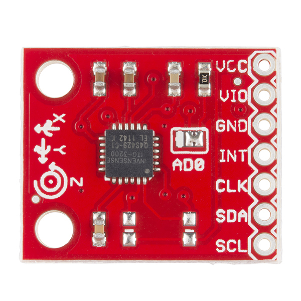
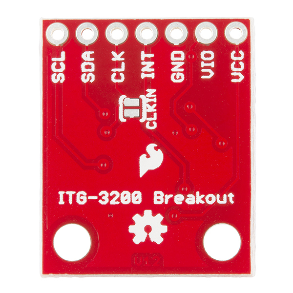
Communication with the ITG-3200 is achieved over a two-wire (I2C) interface. The sensor also features a interrupt output, and an optional clock input. A jumper on the top of the board allows you to easily select the I2C address, by pulling the AD0 pin to either VCC or GND; the board is shipped with this jumper tied to VCC. If you don't plan on using the CLKIN pin, you can short the jumper on the bottom of the board to tie it to GND.
This breakout board is shipped as shown in the images. Note that there are two unpopulated resistors on the I2C lines, these can be added later by the customer if desired.
Not sure which gyro is right for you? Our Accelerometer and Gyro Buying Guide might help!
Replaces:SEN-9801
- Digital-output X-, Y-, and Z-Axis angular rate sensors (gyros) on one integrated circuit
- Digitally-programmable low-pass filter
- Low 6.5mA operating current consumption for long battery life
- Wide VDD supply voltage range of 2.1V to 3.6V
- Standby current: 5μA
- Digital-output temperature sensor
- Fast Mode I2C (400kHz) serial interface
- Optional external clock inputs of 32.768kHz or 19.2MHz to synchronize with system clock
- Pins broken out to a breadboard friendly 7-pin 0.1" pitch header
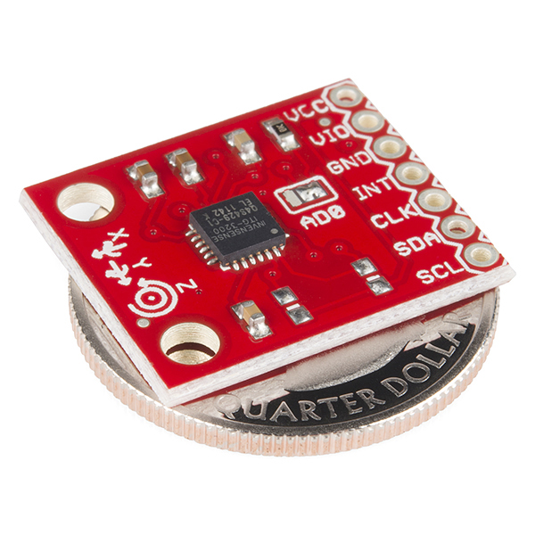
- 0.87 x 0.72" (22.22 x 18.48mm)
- Schematic
- Eagle Files
- Hookup Guide
- Datasheet (ITG-3200)
- Example Code (ATmega328)
- mbed Example
- GitHub
SparkFun Triple-Axis Digital-Output Gyro Breakout - ITG-3200 Product Help and Resources
Core Skill: Soldering
This skill defines how difficult the soldering is on a particular product. It might be a couple simple solder joints, or require special reflow tools.
Skill Level: Noob - Some basic soldering is required, but it is limited to a just a few pins, basic through-hole soldering, and couple (if any) polarized components. A basic soldering iron is all you should need.
See all skill levels
Core Skill: Programming
If a board needs code or communicates somehow, you're going to need to know how to program or interface with it. The programming skill is all about communication and code.
Skill Level: Competent - The toolchain for programming is a bit more complex and will examples may not be explicitly provided for you. You will be required to have a fundamental knowledge of programming and be required to provide your own code. You may need to modify existing libraries or code to work with your specific hardware. Sensor and hardware interfaces will be SPI or I2C.
See all skill levels
Core Skill: Electrical Prototyping
If it requires power, you need to know how much, what all the pins do, and how to hook it up. You may need to reference datasheets, schematics, and know the ins and outs of electronics.
Skill Level: Rookie - You may be required to know a bit more about the component, such as orientation, or how to hook it up, in addition to power requirements. You will need to understand polarized components.
See all skill levels
Comments
Looking for answers to technical questions?
We welcome your comments and suggestions below. However, if you are looking for solutions to technical questions please see our Technical Assistance page.
Customer Reviews
3.5 out of 5
Based on 2 ratings:
Has anyone here figured out the math on converting the read(X, Y, Z) values in the example code to degrees per second? My best guess would be to take read(X, Y, Z) and divide it by 14.375. It would be really helpful to see how its done properly though.
Why are you dividing by 14.375? I divide by 16.384 since the sensor's output data is of 16 bits, 2^15 = 32768 (considering negative and positive values) and then you have to multiply by the sensitivity which is 2000 and it gives me: 32768/2000 = 16.384. But when I integrate the gyroscope values to get the angles I get a 10 degree offset over a 90 degree turn so I compensate this by multiplying the sensor value by 1.125 (90/80) and dividing by 16.384, so the final calculation I do is sensorValue/14.564
The reason I am multiplying by 14.375 is because in the data-sheet it says that the sensitivity scale factor is 14.375. I read somewhere that is what you do to find the angular position roughly... I may be wrong.
Hi. I have some questions here.
Is it necessary or a must to connect the CLKIN to GND if it is unused? Also, do I have to connect AD0 to GND too? Lastly, can I use a pull-up resistor(1K resistor) instead of using a logic level converter to make sure the power input for ITG 3200 is always 3.3V?
Thanks!
I have somewhat of a dumb question if instead of using the sda and scl pins if I hook it up to the analog input will that be safer for my board or does it not matter?
Is this compatible with the Arduino Pro Mini? It has neither SDA/SCL nor A5/A6 pins. Thanks.
I should have studied the board carefully before asking that question. It does have those pins, except they are in the middle of the board.
What's the difference between this and the old board? (Other than $5.00 in the price tag)
Different board only, looks like. It's been redesigned to add mounting holes and be in line with the other boards in the Sensor Kit
Edit: oh, and an extra resistor for the address selection jumper.