- Home
- Product Categories
- Wheels
- SparkFun RedBot Sensor - Wheel Encoder

SparkFun RedBot Sensor - Wheel Encoder
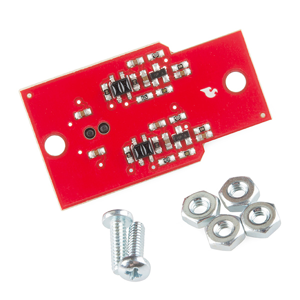
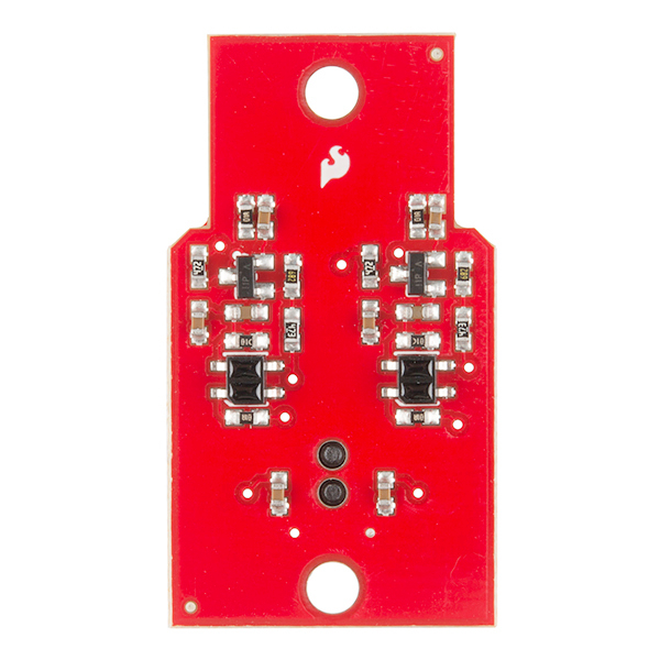
Knowing where your robot is can be very important! The RedBot Wheel Encoder allows you to track the number of revolutions each wheel has made. This sensor works by detecting the movement of small teeth connected to a motor through the reflection of infrared light. By measuring the amount of reflected infrared light you can tell not only how far each wheel has traveled but how fast the wheels are turning.
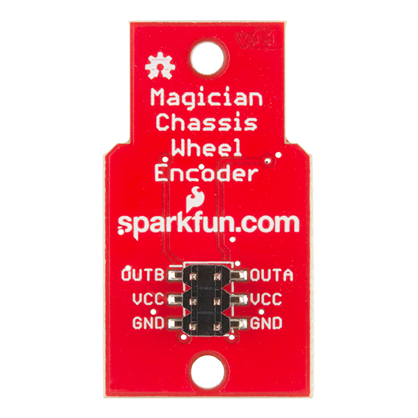
The encoder has a 6-pin header which connects directly to the RedBot Mainboard via female to female jumper wires. Use the included RedBot library to start detecting wheel measurments. Two mounting holes lets you easily connect this sensor to your robot chassis.
Check out the entire RedBot family of products!
- 5VDC operating voltage
- 2x Mounting Holes
- 2 Digital Outputs
- Non-Quadrature
- 1.57 x 0.87 " (40.07 x 22.32 mm)
- Schematic
- Eagle Files
- Wheel Encoder Guide
- Datasheet (QRE1113GR)
- GitHub
- Product Video
SparkFun RedBot Sensor - Wheel Encoder Product Help and Resources
Core Skill: Robotics
This skill concerns mechanical and robotics knowledge. You may need to know how mechanical parts interact, how motors work, or how to use motor drivers and controllers.
Skill Level: Experienced - Your experiences should include working with stepper motors and feedback system. You may need to understand how encoders and more complex control systems work.
See all skill levels
Core Skill: Programming
If a board needs code or communicates somehow, you're going to need to know how to program or interface with it. The programming skill is all about communication and code.
Skill Level: Competent - The toolchain for programming is a bit more complex and will examples may not be explicitly provided for you. You will be required to have a fundamental knowledge of programming and be required to provide your own code. You may need to modify existing libraries or code to work with your specific hardware. Sensor and hardware interfaces will be SPI or I2C.
See all skill levels
Core Skill: Electrical Prototyping
If it requires power, you need to know how much, what all the pins do, and how to hook it up. You may need to reference datasheets, schematics, and know the ins and outs of electronics.
Skill Level: Noob - You don't need to reference a datasheet, but you will need to know basic power requirements.
See all skill levels
Comments
Looking for answers to technical questions?
We welcome your comments and suggestions below. However, if you are looking for solutions to technical questions please see our Technical Assistance page.
Customer Reviews
No reviews yet.
Hi,
This encoder is only unidirectional, right?
Thanks
Yes.
hi is this sensor work for v.2 magician chassis. i want to buy v1 but no more stock http://www.zagrosrobotics.com/shop/item.aspx?itemid=984
No, it will not work for the V2 chassis.
Is it possible to DOUBLE the resolution of the encoder by switching the Interrupt trigger (in the setPinChangeInterrupt routine) between Falling and Rising Edge in the interrupt?
For example when the Rising edge is detected and the interrupt routine is entered, switch the interrupt type to Falling edge for the next transition.
Edit: I see now that an interrupt option exists for "either" edge.
Yes, depending on which interrupts you use. The RedBot library uses the pin change interrupt, which happens on either transition; as it turns out, the nature of the reflective sensor and the wheel encoder can cause some ringing at transitions, which makes it important to do some software filtering.
There's no reason you can't do that, just be careful to only capture one edge at a time.
Do I need to buy one of these for each wheel that I want to encode?
No. This is a full kit for both wheels.
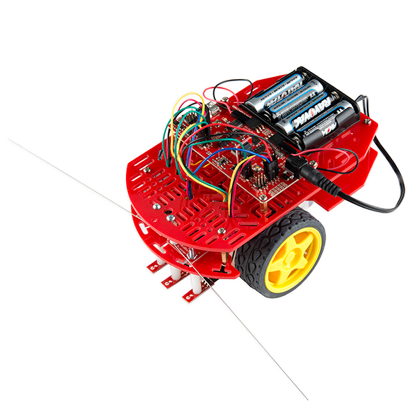
Do note, however, that this kit is for the old RedBot, with the red Magician chassis. If you have a newer model with the black chassis, this won't work.
Hello, i'm tryng to assemble the redbot kit and this wheel encoder....does the dented discs supossed to "touch" the sensors?.... y used the screw and the nuts that came with the sensor and placed them like the pictures....
Hi Sparkfun, I am trying to use this encoder for my university robot fair.But it isn't giving proper number of ticks for each cycle. More or less there are 5 tick difference every time for a full revolution!. Say for example one turn should be 16 ticks but its showing 25 ticks or 20 tick and it is varying each time. So I am not able to count a revolution properly at all. Is there any solution to this problem? Thanks in advance.
Try debouncing the input, slightly. After you see a low-to-high transition, ignore all low-to-high transitions for about 15ms. There are frequently little jitters on the edges, caused by the way the edge moves in and out of the light from the IR transmitter.
The RedBot Assembly Guide Rev 02 https://learn.sparkfun.com/tutorials/redbot-assembly-guide-rev-02/wheel-encoder does not include information about this particular wheel encoder in its tutorial. You would probably need to write code to have this encoder work and look at parts of the old tutorial RedBot Assembly Guide to assembly this encoder => https://learn.sparkfun.com/tutorials/redbot-assembly-guide#redbot-wheel-encoder.
I've got an older version of the RedBot than what is sold today. It is ROB-12032, and it's still sitting in the box waiting to be put together. I notice that the latest version has different wheels for the encoder - they have more teeth. Will this board work with my older RedBot? ---Nevermind. I'd been looking at the picture on the parts list. The actual wheels inside look the same as in the current RedBot version picture.
Probably not. The IR sensors on the encoder board are too short range to work with the 6-notch wheels; that, and a desire to increase resolution, are what drove the change to the new wheels, which are slightly larger in diameter in addition to having more teeth.
I have a couple of those old redbot with those old wheels as well, but also have a couple of this encoders. I am struggling to put them to work. Would it be possible you guys can get me the mechanical size of the new wheels , I would try to cnc them, I appreciate if you can give me a hand on this.
Stupid question incoming: How do I mount this on the chassis?
So far all I've been able to figure out is: use two nuts to elevate the board far enough from the teeth so there's no contact, and screw it in. Is there a "proper" way of mounting this that is consistent with any assumptions in the library code?
Thanks.
Check out the assembly guide, specifically this page, for more details on mounting.
How do you use this? What I mean is, if I wanted to use this with something other than a RedBot Board, say a Raspberry Pi. How would I capture the input from the pins?
sigh. I'm sure you are sick of hearing this. Any plans on clearing out backorder anytime soon?
-PJ
Hi,
This is out of stock now... are you planning to build more and when?
Thanks
We'll have more built up and restocked today. But they are likely to sell out very quickly. If you need one of these soon, I recommend placing a backorder. Once today's batch is built up, production of more will be on hold until we receive a fresh round of PCBs from our PCB fabricator.
I had put one on backorder on 2/1 according to my account, and paid in full. I don't see any notification yet. Did my order somehow get skipped, or maybe it is still processing? Thanks!
We looked into it and your order was printed out this morning by our order pickers. It should be shipping out today or tomorrow, at the very latest. Congrats on being one of the lucky few to get one from the first batch of these wheel encoder boards!
Thank you so much! :)
Thanks very much for the information.
I requested a distributor in Madrid, Spain to try to get this encoder so I can buy it directly from them. They told me they have asked Sparkfun for an estimated delivery date, so I truly hope they can manage to get the part once it is restocked today.
Thanks very much!
For best performance, I'm pretty sure that those sensors should be turned 90 degrees so that the edge of the encoder tooth crosses the center-line of both the emitter and detector at the same time.
A good suggestion; we'll consider rolling that into a future revision.
hii I am from India ...suggest any distributor which sells this product....in India
(I am also from India and I use to buy directly from Sparkfun) You can buy directly from Sparkfun or go to distributors tab and type India in search bar.
If the QRE1113 has a transistor output, why build the amplifier circuit following the reflectance sensor? Why not just route the output from the QRE1113 straight to the microcontroller (an ATmega in this case, right?) - The transistor should only drop about 0.7V, right? Or am I missing something really basic?
Its not an amp circuit, its a pulse shaper/conditioner actually. Its also acting as an inverter. True you can program to whatever levels you need to work with, but from my reading of things this is being used to activate an interrupt routine to count pulses for the wheel revolution. In these cases its usually good to create a known pulsewidth as opposed to taking a variable signal direct from the phototransistor, which could vary depending on how close or far the unit is from the encoder wheel.
Additionally also note these are not quadrature detectors, that could tell you which way an unknown wheel is turning, but a simple pulse counter as wheel direction is known from the drive command.
In fact, if you use the RedBot library, the encoder counts are automatically updated by interrupts and incremented and decremented according to which direction the motors are turning.
Hello, Is there any way that this can be shipped to S. Korea?
Yes, SparkFun ships to South Korea
What about North Korea?
They do not - see https://www.sparkfun.com/static/faq#ship_to_country