- Home
- Product Categories
- Kits
- SparkFun Simon Tilts - Through-Hole Soldering Kit

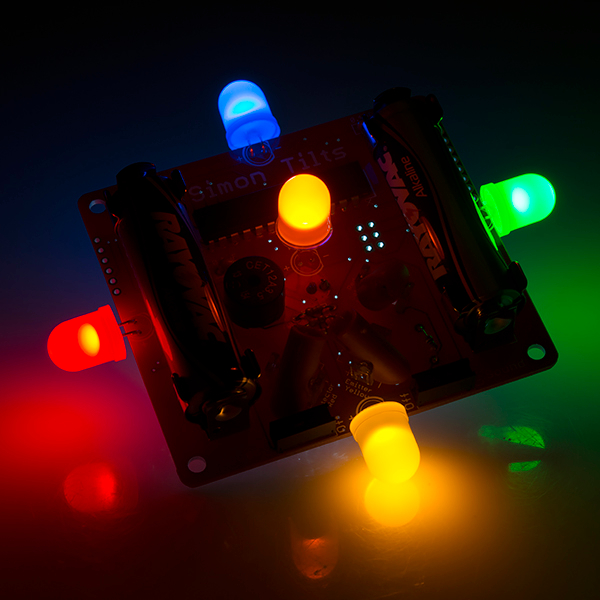
SparkFun Simon Tilts - Through-Hole Soldering Kit
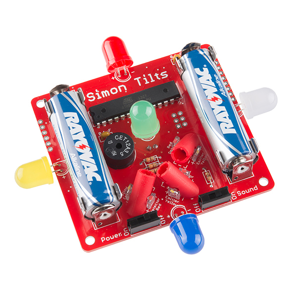
This through-hole soldering kit is very similar to our Simon Says; First, it's a great way to learn how to solder; second, it's a fun game to play; and third, it's a development platform for future projects. The main difference with Simon Tilts is that it involves motion; instead of pressing buttons, the player is challenged to tilt the game. It's a bit of a 3D mind trip, but so much fun to play!
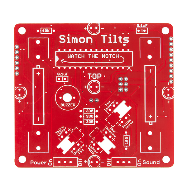
We have taken great care with the PCB design to make it very user friendly. It's a great place to start when you're learning to solder. To sense direction, the kit uses our new custom molded part, the tilt arm. In addition to being fun to watch in action, the tilt arms do an excellent job of sensing the position.
In addition to having a fun game to play, after soldering this kit together you will have a greater knowledge of through-hole soldering and the tools, techniques, and terminology required to populate your own PCB prototype. You will also have a development platform with 7 outputs (LEDs and buzzer), motion sensing (tilt sensor), and serial for debugging.
Note: Be sure to check out the Hookup Guide in the Documents section below for helpful tips and assembly instructions.
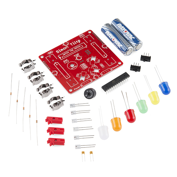
- 1x Simon Tilts PCB
- 1x ATmega328 - pre-programmed with Arduino bootloader and Simon Tilts firmware
- 1x Buzzer
- 2x 0.1μF Cap
- 1x 10K Resistor
- 3x 330 ohm Resistor
- 1x 100 ohm Resistor
- 6x LEDs (blue, yellow, red, green,orange, white)
- 2x Slide Switch
- 4x Battery Clips
- 2x AA Batteries
- 3x BBs
- 3x Tilt Arm
- 3x IR emmitter/detector combo
SparkFun Simon Tilts - Through-Hole Soldering Kit Product Help and Resources
Simon Tilts Assembly Guide
December 3, 2013
This tutorial will guide you through assembling your Simon Tilts PTH Kit.
Core Skill: Soldering
This skill defines how difficult the soldering is on a particular product. It might be a couple simple solder joints, or require special reflow tools.
Skill Level: Rookie - The number of pins increases, and you will have to determine polarity of components and some of the components might be a bit trickier or close together. You might need solder wick or flux.
See all skill levels
Core Skill: DIY
Whether it's for assembling a kit, hacking an enclosure, or creating your own parts; the DIY skill is all about knowing how to use tools and the techniques associated with them.
Skill Level: Noob - Basic assembly is required. You may need to provide your own basic tools like a screwdriver, hammer or scissors. Power tools or custom parts are not required. Instructions will be included and easy to follow. Sewing may be required, but only with included patterns.
See all skill levels
Core Skill: Electrical Prototyping
If it requires power, you need to know how much, what all the pins do, and how to hook it up. You may need to reference datasheets, schematics, and know the ins and outs of electronics.
Skill Level: Rookie - You may be required to know a bit more about the component, such as orientation, or how to hook it up, in addition to power requirements. You will need to understand polarized components.
See all skill levels
Comments
Looking for answers to technical questions?
We welcome your comments and suggestions below. However, if you are looking for solutions to technical questions please see our Technical Assistance page.
Customer Reviews
No reviews yet.
Any plan for 'SMD' VERSION of this kit.
Thanks for bringing this up. We hadn't thought of that yet. We do currently offer the Simon - Surface Mount Stenciling Kit.
Having a kit that teaches both SMD and PTH soldering skills is definitely a great learning tool. Do you think having a second option for a "combo skills" kit would be really popular?
Yes, I think it will be popular.
I really want to no what that component is CET12A3.5 in the include list it just states BUZZER with no link. when I look through your products its used on lodes of other Sparkfun boards but I don’t see it separately. the closest I find is https://www.sparkfun.com/products/7950 are they the same thing. I have a CET12A3.5 that I guess came in one of your kits and it is relay annoying me having no data sheet or reference for what it is.
.
In reading the Github code, i believe there is a comment glitch. For the comments related to the reading of the tlit sensors the documentation reads: // Define an array of "good" readings from the tilt sensors // Notice how 5 and 6 are not included as possibilities in the table above // This is because of the particular angle and placement of the tilt arms // 5 and 6 are impossible, so in an effort to debounce the data, we create the following array // The order of this array is important, because it corresponds with the led_pin[] array.
However it appears that it is 1 and 6, not 5 and 6 that are the non-possible states. :)
Good catch. Thanks! I just fixed it and updated the github repo.
When we first were developing the prototype, we simply streamed the data from the read_position_once() function. This way we didn't really have to think about how the data was coming in. We were mostly concerned that it was outputting a unique value for each position. As it goes sometimes, we rushed to get it working properly and didn't take the time to thoroughly comment each step of the code. Going back to comment was then much more work than it had to be. At first, the table was all mixed up and it took quite a bit of streaming data and thinking to get it all correct :)
We sure appreciate your attention to detail. Thanks again for letting us know about the error!
Oh you are quite welcome. I was reading the code closely because I hacked the Magic! mod into the original Simon, so I was pondering what I could do with this new cool tilt version. See https://www.sparkfun.com/news/1206 for Simon Says Magic! :)
How well do the four LEDs that hang off the sides of the board hold up? It seems like they might get roughed up and eventually snap off if the game is played "vigorously".
They seemed to have held up pretty well with our prototypes. I think as long as your vigorous game play doesn't involve too many drops to hard surfaces, the LED should live on for years. I suppose that's true from most electronics :)
Our first prototypes have seen quite a bit of play time as I've shared them around the office, and none of the LEDs seem to be in danger of cracking off yet. I will say that when I have transported it, I have rapped it in some bubble rap.
Either way, this sounds like a cool opportunity to lazer cut a custom clear box for this thing!
A clear box for this would look awesome! Thanks, I'm looking forward to putting it together.
Why is one pin cut off from the processor chip? There's certainly enough space on the board to have included the pad for that pin...
My guess is it's to "key" the chip so it cannot be inserted the wrong way around. If you do an LED backwards it's only two pins to try to desolder; with the 328 it's a much bigger deal. Yes, they have all sorts of instructions about the notch and stuff which teaches about the proper way to determine correct orientation, but it's not a big loss that they took that pin off.
Exactly right, and boy does it save a lot of trouble when you have a classroom full of 12 year-olds soldering these up!
looks like it also makes a great BOB for the Chorded tilt arms
Indeed. We love to encourage re-purposing our Kits! There's one easter egg in the code to encourage hacking.
Also, I haven't heard of calling a set of sensors "chorded", but it does really make sense. I like it. Music was my major in college, so that term is definitely up my alley :)
I found the Easter Egg!