- Home
- Product Categories
- Kits
- SparkFun Benchtop Power Board Kit

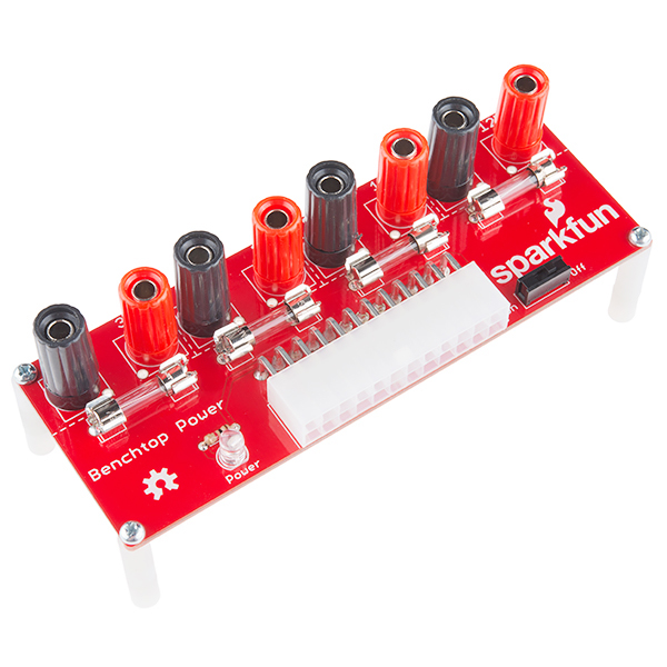
SparkFun Benchtop Power Board Kit
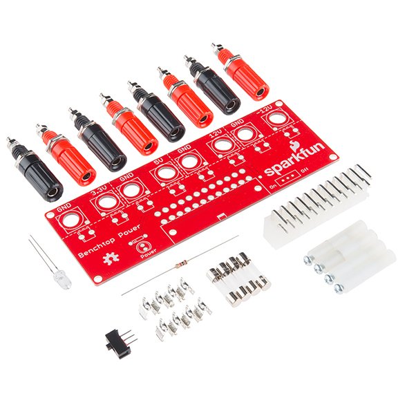
You don’t have the power? Well, there’s no need to ask Scotty – the SparkFun Benchtop Power Board Kit has your back. This board will let you take advantage of your power supply to create a benchtop power supply with enough juice to run almost any of your embedded electronics projects.
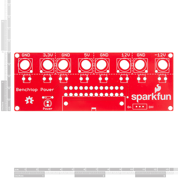
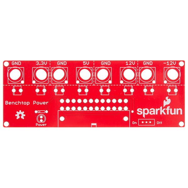
The benchtop power board kit was created to provide quick access to the typical voltages needed when developing physical computing projects (embedded systems). After assembling the kit you'll have access to four different voltages (3.3V, 5V, 12V and -12V) each with their own replaceable 5A fuse. Each power rail has a corresponding ground connection; all of the power rails are brought out to a binding post. The benchtop power board should be powered by a standard computer power supply with an ATX connector. With this rev we have finally added a power switch and made each standoff to a more appropriate height to fit the mounting posts.
This kit is simple to put together and shouldn't take more than 30-45 minutes for a beginner.
- Schematic
- Eagle Files
- Hookup Guide
- GitHub (Design Files)
SparkFun Benchtop Power Board Kit Product Help and Resources
Benchtop Power Board Kit Hookup Guide
November 3, 2014
Need more power? This Benchtop ATX Power Supply Kit should help give you the boost you need to power those energy hungry projects.
Core Skill: Soldering
This skill defines how difficult the soldering is on a particular product. It might be a couple simple solder joints, or require special reflow tools.
Skill Level: Rookie - The number of pins increases, and you will have to determine polarity of components and some of the components might be a bit trickier or close together. You might need solder wick or flux.
See all skill levels
Core Skill: DIY
Whether it's for assembling a kit, hacking an enclosure, or creating your own parts; the DIY skill is all about knowing how to use tools and the techniques associated with them.
Skill Level: Noob - Basic assembly is required. You may need to provide your own basic tools like a screwdriver, hammer or scissors. Power tools or custom parts are not required. Instructions will be included and easy to follow. Sewing may be required, but only with included patterns.
See all skill levels
Core Skill: Electrical Prototyping
If it requires power, you need to know how much, what all the pins do, and how to hook it up. You may need to reference datasheets, schematics, and know the ins and outs of electronics.
Skill Level: Rookie - You may be required to know a bit more about the component, such as orientation, or how to hook it up, in addition to power requirements. You will need to understand polarized components.
See all skill levels
Comments
Looking for answers to technical questions?
We welcome your comments and suggestions below. However, if you are looking for solutions to technical questions please see our Technical Assistance page.
Customer Reviews
4.6 out of 5
Based on 20 ratings:
5 of 5 found this helpful:
Neat little board, good project to get access to power supplies.
Pretty cool little device. Build once and plug and play to save the trouble of having to mod old power supplies. Fairly easy to build too.
I guess it's not a big deal with more modern supplies, I remember when I started converting ATX supplies many of them wouldn't latch on without a healthy load on the 5V rail. If you run across this problem, it could be solved fairly easily by connecting a dummy load at the binding posts. I remember having less frequent problems with the other rails not being voltage stable without their own loads also, but those were kind of a case by case basis.
Words of caution: -I accidentally shorted the back of one of the 90° ATX connector pins to one of the fuse blocks with the probe when carelessly trying to probe for voltages on first use. Power supply went into protection mode so it was fine, but I'd probably recommend protecting the exposed 90° pins (taping, etc) and/or not trying to probe around them. -As a general FYI, I had a few issues on soldering the wire jumpers to the through hole spots in the board for the ground posts. Even with my decent 80W temp controlled soldering station, the heat was getting sucked up by the huge ground plane in the board (nearly the whole board was getting warm) resulting in cold joints. I had to turn my iron up to about 450°C to be able to dump enough heat into the board to get solder to stick well to the PCB pads. -Triple check orientation of fuse holders before soldering. -The black binding posts I got rotated in the board when I was trying to tighten them and their connections down (oval shaped holes supposed to prevent this). I had to hold them with a vice grip. Had no problems with the red ones. -I am also not a fan of how the instructions say to attach the wires to the bottom of the binding posts by crimping it between the two nuts. This is not a very good connection IMO, I ended up crimping a small ring terminal to the wires and secured that instead.
4 of 4 found this helpful:
Love it - mostly
1 complaint: as posted elsewhere, the nuts on the posts are too close.
1 observation: the holders for the fuses have notches and can be put in backwards. The notches keep the fuses from sliding, so they are a good thing.
2 recommendations: Add a USB power connector. Add posts to connect jumper wires. Male posts would be simplest, I think.
All in all, recommended. (and pleasantly surprised I didn't burn anything down while assembling it)
8 of 9 found this helpful:
works well for what it is
Couple of nitpicky things: silkscreened print suggests an orientation that is unlikely, that the powered device is away from the user while the ATX power supply is close to the user.
The banana jacks are spaced at the standard distance, but each GND+Voltage pair is placed very close to its neighbor, which visually creates pairings that don't match the silkscreen.
It works as intended and has a very welcome place on my bench
4 of 5 found this helpful:
Good bench power supply
Works good for all electronic projects. Would like to see a version with a lm317 and variable resistor to create an adjustable voltage out.
1 of 2 found this helpful:
WAS a great gift
This was what our son wanted for a project he is building. He is very happy with the way this has preformed for him.
1 of 3 found this helpful:
Looks nice, haven't been able to use it...
I can't use this with my power supply because it turns out the pin-out on mine is not standard ATX! I have a salvaged Apple G5 PSU (2004) that I want to use as a benchtop supply. I went ahead and modified the design of this board to suit my needs. Go open source hardware! https://github.com/dustMason/Apple-G5-PSU-Benchtop-Power-Supply-Breakout
A champion device!
Considering how inexpensive this kit is, it's very versatile. Minus some awkward angles that you might get with screw down connectors, this thing is almost perfect for what I needed. I've got it hooked up with a nice ATX supply, and it's a perfect stand-in for set voltages needed for my projects.
Overall great product
I wish the connection for the binding post didn't require a wire. I would have much preferred a metal tab of some sorts to solder in place or include some solder eyelets. Other than this issue I find that the product is really good. I have used it for many of my projects now and i have only owned it for a couple of weeks. The fuses saved me big time. I accidental shorted a couple of wires on my breadboard and the fuse blew instead of melting components.
Very useful
It lets you easily built a cheap bench top power supply. Instead of hacking up a power supply, you can just plug and play.
Great little project!
Assembled in about 30-40 minutes and I only have basic soldering skills. Be aware no paper instructions are included, but the online instructions are great. Also, the plug receiver has 24 slots but my power supply had only a 20 pin plug. Took a couple attempts to find the right slots to leave open but I managed. Works exactly as advertised.
Great idea! Some poor parts.
Great idea! Excellent board. I bought two of these. One for myself and one for a future son in law. Assembly went like a dream right until the end. Everything worked. Then I got to the banana jacks. One had stripped threads before I started. Four of the remaining 15 stripped out as I tightened them and three of the metal threads stripped when i attached the wire to them. Sprakfun made good on the replacement parts. I was able to replace six faulty posts and they are all nice and snug now.
Sorry to hear that you had trouble with the jacks. I'm going to be contacting you directly about getting those replaced for you.
Pretty Darn Good!
Assembled it (mostly) according to instructions. The instructions are great, BTW, you should follow them, but If you're going to depart from them, as I did, you should still run through them in your head. My only complaint was that they were short a couple of the smaller bolts that secure the banana plugs. I didn't need the stand-offs, so I used the bolts from them, which were the same. Altogether, a BIG time-saver. I especially like having commonly available fuses protecting the power supply. I wouldn't have thought of that on my own, 5 stars!
Excelent ATX breakout board
I love kits, and this power board is easy to assemble. A very handy way to provide bench power.
It was a fun build and works great!
Only gripe I have is that the screws for the stand offs were nowhere near long enough to fit 2 standoffs on. The screws only go through half of a standoff. Unless I grossly misread the instructions multiple times, I think I got the wrong screws. No big deal though, just a quick trip to the hardware store. 🙂
Great power supply for breadboard projects
It went together fast and easy. The only change I did from the instructions was putting ring terminals on the ends of the wires. Then there would be no chance of them coming loose. Now I have more power for projects and rock solid stable voltages. Great product!
Good kit. Will use it as part of training
Easy to assemble and works fine.
Very easy to assemble and it works great!
I'm new to electronics in general. This was a great project to start honing my soldering skills. It works exactly as described. I couldn't be happier with this power board. Thanks!
Great idea.
I had one of these lying around for quite some time and finally got around to building it. It was a little difficult to build and so I went to the online documentation on the SparkFun site to get answers.
I discovered that they had revved the board. The on/off switch seemed like a really good idea. After getting my answers & building the board, I decided to get & build the second version as well.
The improvements .... - They provided relief around the ground holes so they are much easier to solder. - They made the binding post holes oblong so they are much easier to install - The on/off switch is a nice addition and works well.
Pros - This works well with a standard ATX both 20 pin and 24 pin cable. (make sure that you check all the pins to ensure that they match as there are non standard power supplies out there. If you use the 20 pin atx, plug it into pins 1 & 13 on the board.) - Really slick idea. Makes the power supplies for old PC's conveniently re-usable and makes for a really powerful bench supply..
Con - The nuts on the binding posts are too close together. You have to be sure that the power and grounds are not shorted.
Notes - Check your power supply specs. Some of them provide way more than 5 amps so you could change fuses. - Making the wires to the binding posts 1.125 inches long, stripping a little off one end to go through the board, and stripping enough of the other end to make one revolution around the post works well, - The board is a little longer so it won't fit into the shipping box of the previous rev without modification and they didn't provide the template on the box for the new rev. (On the previous rev, you could make the shipping box into the power supply "case" as they marked cut outs on the box.)
Why does this board have "Mean Well LED Switching Power Supply - 5VDC, 8A" as an "essential product required in order to function properly" ? I can't see how they would work together.
Sorry about that, it shouldn't have been there. All updated.
Pretty nice and liking it so far, but could use improvements.
It's kinda sucky that you have to solder your own wires to the posts. As others have said, the spacing on the posts is illogical too. And since all ground/black posts are the same, they might as well be left out and just include 1 or 2 black ground posts and the rest red (most of us don't need multiple voltages at the same time).
The provided fuses are too low, some spares would be nice. I burned one out quickly and didn't feel like going out to hunt for new ones (where I live I can't order online easily). So I just added a wire to bypass the fuse. I'll live with the consequences.
Also it would be nice to have a few USB ports on it, so you can power/recharge USB devices on it too.
A rocker switch or push switch would be nice instead of the small slide switch.
Does Sparkfun sell a power supply to use with this? If not, what are some recommendations?
We don't, but any standard ATX power supply should work. You can find then in an old computer or at a computer store.
If I replace the 5A fuse with say a 20A fuse on the 12V rail, what is the maximum current this board can provide through 12V? Has it been load tested for 20A?
I have a big power requirement (~200W off of 12V) project I'm looking to use this for.
We have not tested it for that, but there may be users in the forums that can point you to their own testing results. You can use a PCB Trace Width Calculator to determine what a PCB can handle.
hmm, it still doesn't include load resistors to keep the PSU stable and/or on...
Yeah, that's a huge miss, especially considering the big (ceramic?) ones are not always just laying around.
To have one on the board, instead of at the ends / terminals would be very helpful.
For those wondering, or experiencing issues, a PSU may require minimum loads on one or more lines. Typical load values are 1A on +12v, 0.3A on 5v, and 0.5A on 3.3v. If there are multiple +12v lines then each may require a 1A load. Some PSUs don't need the loads. Some PSUs will just turn off, others will stay on but have out of spec voltages, and others don't need loading (they're internally loaded).
Right; I think this is the guide I used when converting mine:
http://www.instructables.com/id/Convert-A-Computer-Power-supply-to-a-Bench-Top-Lab/
It's super useful, but be careful, obviously. I needed the Resistor, and its likely with newer switching-mode PSUs, you will need it too. This kit is nice though, and requires much less time and danger. You can likely just place the load resistor across a different set of pins on the power supply ( like at one of the standard 4 pin molex connectors) and not busy up such a handsome board, with a blocky dangly resistor.
Is there any chance to buy just the PC board from this kit?
Very disappointed in this kit. The binding posts are very poor quality...the worst I have ever seen in 35 years of electronics professional and hobby work!. The function seems to work fine, but while the spacing between the pairs of post (Blk/Red) is fine, the spacing between adjacent pairs is dangerously close and you can short the + of one voltage to the ground of another (I. e. they are common grounds!) because the hex nuts on the back of the too close binding posts can short! I had to work hard to get the nuts to thread correctly on 3 of the posts.
Providing ALL 5Amp fuses when clearly the amperage of a typical PC power supply is very much higher (or lower) then 5 Amps. Way too high current for some voltages and very undersized for the 12V, high current outputs.
Having to ADD jumper wires to connect the binding posts to the circuit seems a bit cheap as will. Pick a binding post style the can be bolted on and makes connection from the start.
As for function, I can say it works, safety issues aside, but could be sooo much more. 1) Fix the spacing, provide better and correct binding post style, reasonable fuse sizes or at least some instruction to warn low knowledge users. 2) Provisions in the circuit board for adding Voltage and current monitoring would be fantastic. Don't populate or sell the extra bits as an add-on, but at least provide the holes and simple traces to add external wires to meters and a cut trace position to add a through-hole sense resistor in series.
Have to say that I love 99% of the product I get from sparkfun and really like their support of the hobbyist Makers out there. Please see if you can clean this one up, as I could use more, if the issues are resolved.
My 2 cents.
I agree with Rigby (In Reviews). This seams a little backwards and the ATX cable assay. is going to be in the way. I'd like to see this with the ATX on the back and perhaps make it so it would add on to the big breadboard. https://www.sparkfun.com/products/12614
That would be awesome!
Star my post if you didn't look at the orientation of the fuse clips. Le sigh...
Hello,
I plan to use this item with Corsair HX520W
http://www.silentpcreview.com/article692-page1.html
to power up a 12V/14A RGB LED strip. In the power description,
http://media.www.cdrinfo.com/Sections/Articles/Sources/C/Corsair%20620W%20PSU/Images/2.png
it says this power supply unit can provide 18A from each of its three +12V rails.
Does this plan doable?
Your time and input will be much appreciated. Thanks in advance.
If you are only powering up a single strip, you should have no problem with this set up. Though I would recommend verifying exactly what comes with that power supply you listed - it looks like it may already come with connectors for the 12V rail, which may negate the need for this product.
Thanks for the reply. Yes, there is an 8-pin 12V rail readily on this PSU but I will also need a 5V too so I think this Benchtop Power Board Kit will be handy for the project.
My worry is at the size and length of wire needed for connecting the 12V common of RGB strip to the 12V banana plug of this board. Would it be appropriate to use a 1kV/3A stranded wire:
http://www.ebay.co.uk/itm/10-Metres-Equipment-Wire-Cable-16-0-2mm-Stranded-3A-1KV-11-Colours-CUT-LENGTH-/360856697435?pt=LH_DefaultDomain_3&var=&hash=item5404bc3a5b
I used a cable size calculator here:
http://www.solar-wind.co.uk/cable-sizing-DC-cables.html
it suggests 0.8 meters wire length - is this the right way to calculate the wire length?
You need to figure out how much wire length you need for mounting or assembling your project. Based on that, then you can figure out the gauge of the wire you need to make sure your connections can handle the power draw through them (and you won't get too much resistance from the wire itself - that can affect performance of the LEDs).
This is awesome! I've been using a spare ATX power supply for my high current needs for a while, but I've been snipping the molex connectors off the end of the cables to gain access to the rails. This makes things MUCH easier.
You need to add some pads for the user to install multiple filters, such as band-stop, high-pass, and low-pass filters, so they can filter out power supply noise. These should be optional, of course, and the filters required will wind up being unique to each supply, but to make these supplies genuinely usable for more advanced projects, finding the right frequencies to snuff out to provide clean power is a must. Maybe one through-hole set of pads, and 3 surface-mount sets of pads, per output?
Take some random power supplies, give them a load, and put it on a spectrum analyzer. You will see all kinds of crazy noise spikes. These should be filtered out before someone uses it on a serious project. And they won't be the same across supplies, either.
The user should have the option to filter out his supply's noise with a set of pads for that purpose. It's a cheap, affordable improvement that adds a lot of value.
Wow, thanks for all the feedback everyone! This is great to see all the feedback, as the original wasn't one of the more popular products. We will definitely keep this all in mind for the next revision.
I've heard that most ATX supplies currently being sold no longer require the resistor across the 5v line to power up. YMMV on this, but it was the case with the last supply I tried that delivered a measured 12.3v with no load. That might be just about right because under full load it might be expected to drop 300mv due to an internal current sense resistor. Note that there may be a brown wire next to the 3.3v orange ones that needs to be connected to the 3.3v lines. This would be a voltage sense line, I didn't check the schematic here closely enough to see if that was included. Might be similar sense line for the 5v supply as well.
I assume that the 1K resistor protecting the power indicator lamp is an insufficient load to keep an ATX supply "awake".
While it may be true that new ATX supplies do not require a resistor, the logical thing to do is to save an old one from the land fill. Used supplies are ubiquitous and it would be silly to buy a new one just to run this board.
Presumably most people will use an old, cheap, or free ATX supply, so the likelihood is they will need to add a load resistor to this board.
This simple soldering project seems aimed at beginners. Setting them up for failure by leaving out the option of, or an explanation about how to install or whether it needs a load resistor is not the most kosher thing I've seen Sparkfun do. This is a rare failure from Sparkfun, but it is all the more glaring because they didn't correct it in this second version of the product.
Forgive me, but I disagree. Part of the learning process includes failure due to unforeseen consequences. It teaches one an important lesson about planning and thoroughly considering potential pitfalls when building something new, especially using old equipment. It's an important tool for learning to be more cautious and not simply assume that all possible problems have been accounted for. Coddling beginners and trying to anticipate every possible issue they will encounter and solving it for them ahead of time is a disservice to developing their problem solving skills.
If one out of four beginners burns up or fails to power up an old ATX power supply then one out of four beginners will either learn from that failure and benefit from the early lesson, or they will give up before they've wasted too much time in a hobby they weren't really interested in or ready for.
This is an edge case. Assuming that most will be using a much older design for ATX PSUs that require a 5v load is silly. If the voltages are unstable and some users need a resistive load on the PSU to stabilize the output, they should be given the opportunity to investigate and discover that need on their own. Maybe in the process they will learn something about the PSUs they are trying to use and why it needs that load.
I'm not saying don't give them the answer, I'm saying let them ask the question first. That is how people learn.
Your points are not unwelcome and if the beginner you are thinking of is a freshman in an EE program, you are exactly right. But before I throw in the towel and completely agree with you, I'd like to say that there are plenty of other projects in the EE curriculum that separate the dedicated from the dillitantes.
I have a less sophisticated beginner in mind. I teach eleven year olds. But I have to admit that their power supply needs can be met with a wall wart adapter, equally ubiquitous at thrift stores, if not more so than ATX power supplies. If they need something more stable, or adjustable, they can certainly figure out how to wire up an LM 338, and that's probably a safer option anyway.
Cheers,