- Home
- Product Categories
- Arduino Shields
- SparkFun GPS Logger Shield

SparkFun GPS Logger Shield
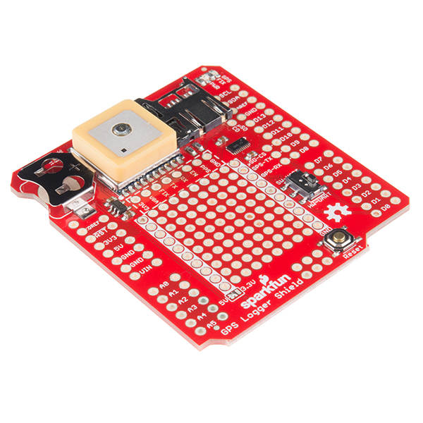
The SparkFun GPS Logger Shield equips your Arduino with access to a GPS module, µSD memory card socket, and all of the other peripherals you’ll need to turn your Arduino into a position-tracking, speed-monitoring, altitude-observing wonder logger. The shield is based around a GP3906-TLP GPS Module – a 66-channel GPS receiver featuring a MediaTek MT3339 architecture and up to a 10Hz update rate. The GPS module will stream constant position updates over a simple TTL-level serial port, which you can then log to a µSD card and/or use for other purposes.
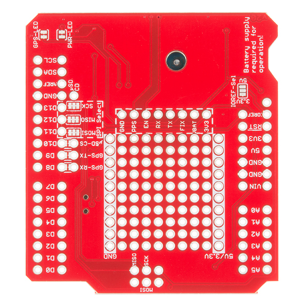
Everything on the shield is highly configurable: A switch allows you to select the GPS module’s UART interface between either hardware or software ports, the µSD card operates over a hardware SPI port, which should be compatible with most Arduino layouts, and extra prototyping space should allow you to add those last, few components you need to complete your project. The GPS Logger Shield’s main voltage supply is taken from the Arduino 5V header pin. This voltage is regulated down to 3.3V, which is supplied to both the GPS module and the µSD card. These two components should consume, about 30mA on average, but they may very occasionally spike to around 100mA. We also highly recommend a 12mm Coin Cell Battery, which fits into the GPS Shield’s battery holder.
Note: The shield does not come with headers installed; we recommend the Arduino Stackable Header Kit.
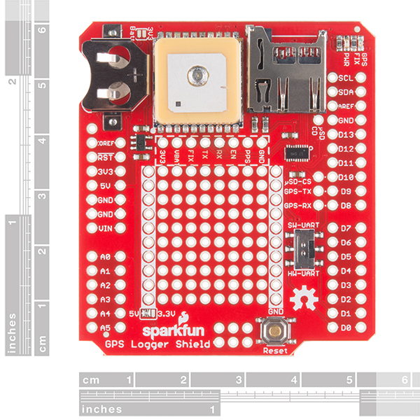
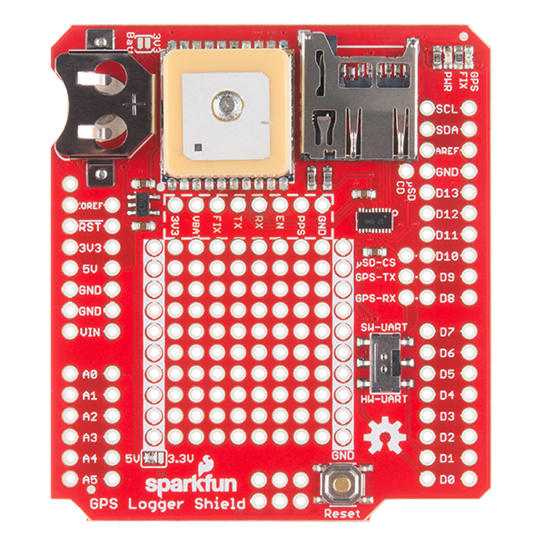
- On-Board GP3906-TLP GPS Module
- 12mm Coin cell battery socket
- µSD memory card socket
- Standard Arduino sized shield
- Prototyping area
- GPS Module Pins Broken Out
- Arduino reset button
- UART switch controls serial communications
- Schematic
- Eagle Files
- Hookup Guide
- Datasheet (GP3906)
- GitHub
SparkFun GPS Logger Shield Product Help and Resources
GPS Logger Shield Hookup Guide
February 11, 2016
How to assemble and hookup the SparkFun GPS Logger Shield. Never lose track of your Arduino again!
GPS Basics
December 14, 2012
The Global Positioning System (GPS) is an engineering marvel that we all have access to for a relatively low cost and no subscription fee. With the correct hardware and minimal effort, you can determine your position and time almost anywhere on the globe.
Changing the Update Rate of the GP3906 Module
If you want to fiddle around with the update rate for the GPS module on this shield you can do so by sending MTK NMEA commands via the UART pins for the module we have broken out on this shield. Here are a few helpful links to get you started:
Please note, you will need to change the baud rate of the module to run at a faster speed in order for the module to accept the higher update rate commands.
Standby mode.
Standby Mode: In this Mode the receiver stops navigation and internal processor enters standby state current drain at main supply VDD is reduced to 200 μA typ.
Standby Mode is entered by sending NMEA command: $PMTK161,0*28. Host can wake up the module from Standby Mode to full Power Mode by sending any byte via host port.
The shield only draws about 7mA after the command is issued.
Core Skill: Soldering
This skill defines how difficult the soldering is on a particular product. It might be a couple simple solder joints, or require special reflow tools.
Skill Level: Noob - Some basic soldering is required, but it is limited to a just a few pins, basic through-hole soldering, and couple (if any) polarized components. A basic soldering iron is all you should need.
See all skill levels
Core Skill: Programming
If a board needs code or communicates somehow, you're going to need to know how to program or interface with it. The programming skill is all about communication and code.
Skill Level: Competent - The toolchain for programming is a bit more complex and will examples may not be explicitly provided for you. You will be required to have a fundamental knowledge of programming and be required to provide your own code. You may need to modify existing libraries or code to work with your specific hardware. Sensor and hardware interfaces will be SPI or I2C.
See all skill levels
Core Skill: Electrical Prototyping
If it requires power, you need to know how much, what all the pins do, and how to hook it up. You may need to reference datasheets, schematics, and know the ins and outs of electronics.
Skill Level: Rookie - You may be required to know a bit more about the component, such as orientation, or how to hook it up, in addition to power requirements. You will need to understand polarized components.
See all skill levels
Comments
Looking for answers to technical questions?
We welcome your comments and suggestions below. However, if you are looking for solutions to technical questions please see our Technical Assistance page.
Customer Reviews
4.3 out of 5
Based on 4 ratings:
Easy to setup and start using
Easy to setup and start using, and the fact that the programs are on the website allowed me to start logging and testing.
Problem
As you probably know I got two of these. The second one had a problem with the battery or battery assembly. The battery voltage (no load) was 3.1V. That could be the problem. Regardless, I had to bypass the battery with the jumper pad and put the supply 3..3V on the VBat to get it too work. Biggest complaint is it took me a while to figure out what was wrong! You might have an old or bad batch of button cells. Your schematics don't show the battery connection!
But I got them both to work and they work well, good instruction set, I am using them to measure latency in a 3.5 mile ethernet connection between a dispatch console and radio system that uses VoIP.
Have a question about battery power and 3V jumper
Can't seem to post in Forum so I'm looking for help with advise. Did not have a 3 V Battery so I used the 3VDC jumper and powered the GPS sensor that way.
Now I have a 3VDC battery and need to know if I should cut/de-solder the jumper.
Any advise would be appreciated.
Why not pick a GPS module that has external antenna input with a uFL connector? Limits your application possibilities to just use the module's antenna.
Hi there,
I have a question:
If I wanted to use this with a Raspberry Pi 3 do I need to reroute the TX,RX Pins, or I can leave them as factory?I put a header next to the GPS (where its pinout) and connect it from here to the RPI, but I don't get the gpsfix led blinking, only the power led lighting.
Thanks for your reply,
I bought one of these on Amazon to use as part of an Arduino based NTP server. It's a great little board and I really love how easy it is to customize (including breaking out the serial I/O so I can use whichever pins I want), but there are a couple issues. First and most importantly, this should include a connector for an external antenna, I can get a good GPS lock indoors here but that isn't the case for everybody. Second, I was not able to get this to fit snugly onto an Arduino UNO, MEGA 2560 or the ethernet shield with the included stackable headers. What I did was insert them into another spare set of stackable headers I already had, then plugged that into the ethernet shield, it sits a little higher off the board than I'd like but it does fit securely.
Hi there, it sounds like you are looking for technical assistance. Please use the link in the banner above, to get started with posting a topic in our forums. Our technical support team will do their best to assist you.
That being said... the GPS module used on this shield doesn't have the ability to attach an external antenna (i.e. that isn't possible without getting into tuning a ceramic antenna). As far as the stack-ability goes, we don't produce this shield with populated headers, so it sounds like the Amazon seller might have soldered them on crooked (with a lean). It should be fairly simple to rework (i.e. correct), just be careful of overheating the board.
Hi,
Does this unit has its own RTC or should we externally integrate one? In the schematics I could not see it and need to make sure.
Thanks,
Fatih.
There is no RTC, but if using GPS you can grab time from the GPS unit which I believe was the intention.
Is there any information about the max altitude this module will work up to? I'm looking at using it for high altitude ballooning and I wanted to make sure it works up to at least 100,000ft before using it. Quick skim over the datasheet didn't provide any altitude info...
Is there an arduino board this is supposed to fit snugly on? On my uno R3 it gets blocked by the USB port, and on my redboard by the power port. I have extra tall headers so its not a big problem, just seems like it should be able to sit snugly
Sorry I didn't see this before now. This should fit on any Arduino Uno R3 or the SparkFun Redboard. You do have to solder headers to the shield though. Once the stackable headers are soldered on it sits higher on the boards that it looks like at first glance.
I'm stepping my game with arduinos and now I am looking to 3,3V arduino. Unfortunately, I found that most of the shields (like this one) use 5V as main. Is there any tutorial to hack this shields to be fed with 3,3V?
This shield is made to be compatible with most 3.3V or 5V Arduinos - I bet yours'll work. The board takes its power in from what is usually the Arduino's 5V pin. But even if your Arduino has 3.3V there, that should still be enough to feed the 3.3V LDO regulator on-board.
You'll also need to make sure the IOREF pin is tied to 3.3V as well. Or, if your Arduino doesn't have an IOREF pin, you can set the IOREF jumper to 3.3V on the shield. There's more info in this section of the hookup guide.
Thanks for the replay. Actually I'm working with a Redboard and looking to 3.3V arduino pro since the majority of the sensors that I'm working with are 3.3V.