- Home
- Product Categories
- Arduino Shields
- SparkFun ProtoShield Kit

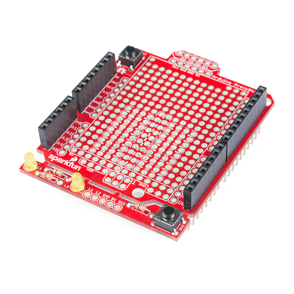
SparkFun ProtoShield Kit
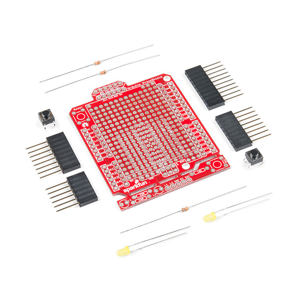
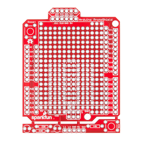
The SparkFun ProtoShield Kit lets you customize your own Arduino shield using whatever circuit you can come up with and then test it to make sure everything is working the way it should! The SparkFun ProtoShield Kit is based off the Arduino R3’s footprint that allows you to easily incorporate it with favorite Arduino-based device.
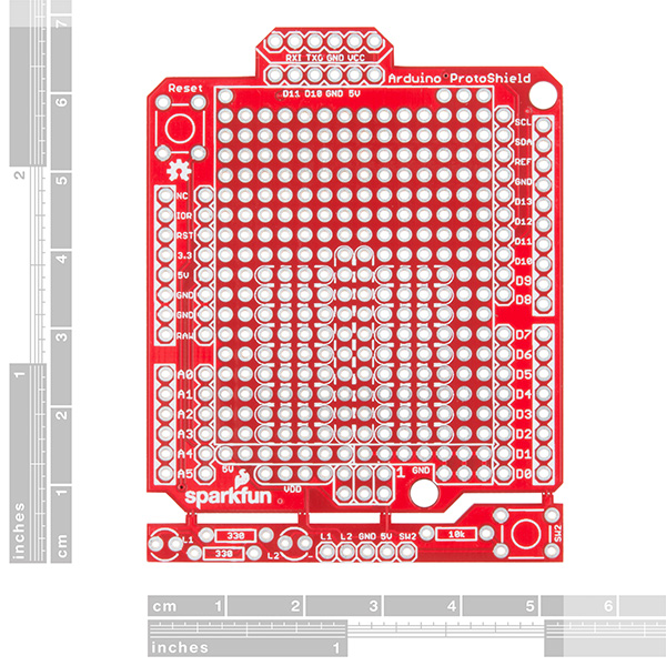
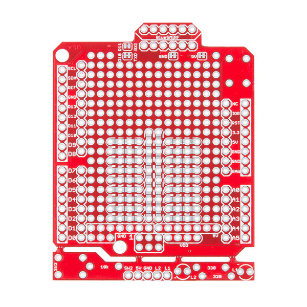
One of our favorite features with this version of the ProtoShield Kit is the solderable-like breadboard prototyping area! Half of this area was designed with a breadboard in mind. On the underside of the shield you will be able to see open jumper pads between each through hole to make a connection like a breadboard. Once you add a component, simply add a solder jumper between holes to make a connection. For those that prefer the standard prototyping pads, we left the other side (near the BlueSMiRF and Serial UART ports) as is.
We have also moved the prototype testing components (those used to make sure your circuit works effectively) off of the "mainland" of the shield and onto a ProtoSnap styled, removable PCB. On this test area you will find soldering areas for the two yellow 3mm LEDs (as well as pins to control and power them), two 330 Ohm resistors, a 10K Ohm resistor, and a pushbutton.
Note: Since this product is a kit, assembly and a basic knowledge of soldering will be required. The SparkFun ProtoShield Kit does not come pre-assembled.
- Arduino R3 Footprint
- Soldering Kit
- Solderable-Like Breadboard
- BlueSMiRF or Comparable 6-pin
- Detachable Test Area
SparkFun ProtoShield Kit Product Help and Resources
SparkFun Arduino ProtoShield Hookup Guide
May 17, 2018
The SparkFun Arduino ProtoShield PCB and ProtoShield kit lets you customize your own Arduino shield using whatever custom circuit you can come up with! This tutorial will go over its features, hardware assembly, and how to use the shield with an Arduino R3 footprint.
Core Skill: Soldering
This skill defines how difficult the soldering is on a particular product. It might be a couple simple solder joints, or require special reflow tools.
Skill Level: Rookie - The number of pins increases, and you will have to determine polarity of components and some of the components might be a bit trickier or close together. You might need solder wick or flux.
See all skill levels
Core Skill: Electrical Prototyping
If it requires power, you need to know how much, what all the pins do, and how to hook it up. You may need to reference datasheets, schematics, and know the ins and outs of electronics.
Skill Level: Rookie - You may be required to know a bit more about the component, such as orientation, or how to hook it up, in addition to power requirements. You will need to understand polarized components.
See all skill levels
Comments
Looking for answers to technical questions?
We welcome your comments and suggestions below. However, if you are looking for solutions to technical questions please see our Technical Assistance page.
Customer Reviews
4.7 out of 5
Based on 3 ratings:
2 of 2 found this helpful:
Might not want to follow the hookup directions exactly
Got your attention? Good. First of all, let me state that it's obvious to me that a lot of thought went into designing this product. It's extremely flexible, as I discovered when I was outlining how to use it. Since I have to be quite careful with the very limited funds that I can spend on my 'toys', I spent a couple of months planning out how to use this kit before I even got it. That was time well spent, and I would recommend others do the same. Otherwise, you are likely to make mistakes. Let me outline my suggestions: 1) Don't put it together when you first get it. As a matter of fact, soldering the headers on is the absolute last thing you want to do. That's because often when one is mounting parts, you need to be able to come in from various sides to put soldering iron to solder, wire, and part. Headers just get in the way - so put them on dead last. 2) Download the Eagle design files first instead. Use the Eagle PCB design program to interactively place different parts on the board, and see if they will fit where you think they should go. 3) Do several dry runs of placing parts. Eagle is great for a preliminary overview, but physically seeing it in reality helps even further. You will notice things with placement that didn't popup earlier. Example: The large power connector on an Arduino, though not needed for most uses that I've had, does get in the way of that part of the protoboard right above it. (I ended up using a Dremel tool to cut away at the power connector on the RedBoard Turbo, just so I could use that part of the protoboard.) 4) Don't be afraid to cut traces that need to be cut. I used this with a Redboard Turbo, which is a 3.3 volt device. Because of that, I had to be careful of the ICSP socket, which I needed wired up because I needed SPI. But I didn't just cut off the traces to the 5 volt pin there. I ended up cutting the trace closer to where it branches off. That way that voltage line is used to provide power to the extra prototype area with the extra button and LEDs. 5) You don't have to put the two LEDs in. I used one of the LED footprints to mount a 2 pin JST connector, so I could use that to feed power to my entire board! The board design allows one to pull tricks like this. 6) The 6 pin connector at the one end doesn't have to be used for a serial interface. I split it into two 3 pin interfaces: one for an IR detector, and the other for an LCD display. I ended up being able to fit all of the following on the board for my project: two quad bidirectional level converters, an IR detector header, an LCD connector, an I2C EEPROM, an I2C header for a BME280 temperature/pressure sensor, hex schmitt trigger IC for a dual quadrature encoder interface with a connecting 8 pin header, an SPI interface for an inclinometer sensor, a JST power connector, two headers for hall effect sensors, with an additional header for a latching hall effect sensor, and of course, the extra button for telling the software to get out of a crash condition. The fact that this kit even allows me to do all that, with the extra parts I had to get of course, says a lot about how well the board was designed. (Hey, I've still got some free pads left on the board!) My only quibble is a small one. I would have liked to see one of those trace cuts available for the reset pad on the ICSP header. I wanted to convert that to an SPI chip select line, and had to carefully cut the right trace to do it. So, do your homework first, and have fun!
These are great tips! Thanks for your review. :-)
I did not use it. I found the Adafruit proto shield v6 a better fit for my needs.