- Home
- Product Categories
- IMU
- SparkFun 9DoF Sensor Stick

SparkFun 9DoF Sensor Stick
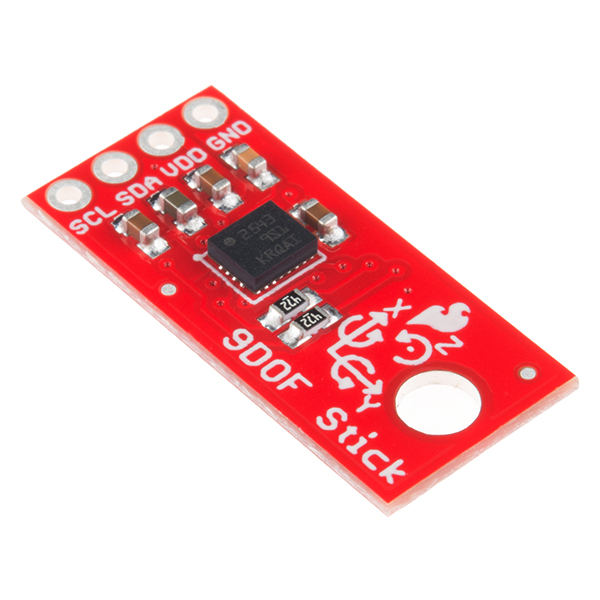
The SparkFun 9DoF Sensor Stick is an easy-to-use 9 Degrees of Freedom IMU. The Sensor Stick deftly utilizes the LSM9DS1 motion-sensing system-in-a-chip, the same IC used in the SparkFun 9DoF IMU Breakout. It houses a 3-axis accelerometer, 3-axis gyroscope, and 3-axis magnetometer – nine degrees of freedom (9DoF) in a single IC!
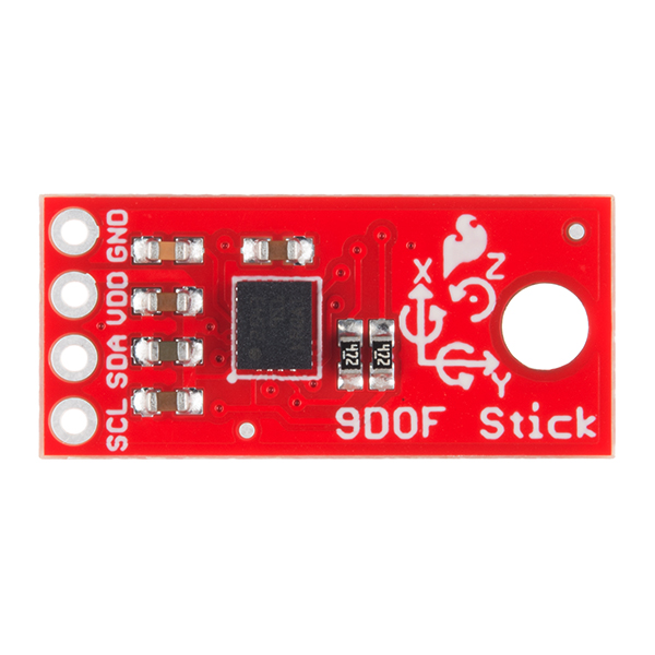
The onboard LSM9DS1 from STMicroelectronics is equipped with a digital interface, but even that is flexible. The biggest difference between the two boards, besides the slimmed down 0.9"x0.4" footprint, is the number of broken-out pins, with the Sensor Stick featuring only four for quick setup and ease of use.
The LSM9DS1 is one of only a handful of ICs that can measure three key properties of movement – angular velocity, acceleration and heading – in a single IC. By measuring these three properties, you can gain a great deal of knowledge about an object’s movement and orientation. The LSM9DS1 measures each of these movement properties in three dimensions. That means it produces nine pieces of data: acceleration in x/y/z, angular rotation in x/y/z, and magnetic force in x/y/z.
Each sensor in the LSM9DS1 supports a wide spectrum of ranges: the accelerometer’s scale can be set to ± 2, 4, 8, or 16g, the gyroscope supports ± 245, 500, and 2000°/s, and the magnetometer has full-scale ranges of ± 4, 8, 12, or 16 gauss.
- 3 acceleration channels, 3 angular rate channels, 3 magnetic field channels
- ±2/±4/±8/±16g linear acceleration full scale
- ±4/±8/±12/±16 gauss magnetic full scale
- ±245/±500/±2000dps angular rate full scale
- I2C serial interface
- Operating Voltage: 3.3V
- Schematic
- Eagle Files
- Hookup Guide
- Datasheet (LSM9DS1)
- GitHub
SparkFun 9DoF Sensor Stick Product Help and Resources
9DoF Sensor Stick Hookup Guide
August 25, 2016
How to connect and use the SparkFun 9 Degrees of Freedom Sensor Stick with an Arduino
Core Skill: Soldering
This skill defines how difficult the soldering is on a particular product. It might be a couple simple solder joints, or require special reflow tools.
Skill Level: Noob - Some basic soldering is required, but it is limited to a just a few pins, basic through-hole soldering, and couple (if any) polarized components. A basic soldering iron is all you should need.
See all skill levels
Core Skill: Programming
If a board needs code or communicates somehow, you're going to need to know how to program or interface with it. The programming skill is all about communication and code.
Skill Level: Competent - The toolchain for programming is a bit more complex and will examples may not be explicitly provided for you. You will be required to have a fundamental knowledge of programming and be required to provide your own code. You may need to modify existing libraries or code to work with your specific hardware. Sensor and hardware interfaces will be SPI or I2C.
See all skill levels
Core Skill: Electrical Prototyping
If it requires power, you need to know how much, what all the pins do, and how to hook it up. You may need to reference datasheets, schematics, and know the ins and outs of electronics.
Skill Level: Rookie - You may be required to know a bit more about the component, such as orientation, or how to hook it up, in addition to power requirements. You will need to understand polarized components.
See all skill levels
Comments
Looking for answers to technical questions?
We welcome your comments and suggestions below. However, if you are looking for solutions to technical questions please see our Technical Assistance page.
Customer Reviews
3.6 out of 5
Based on 8 ratings:
1 of 1 found this helpful:
Very nice version of the larger board for better price
The IMU has been working just fine. I do wish their was protection against over voltage and even reverse voltage as that seemed to be the only weakness experienced with my students. But that statement can apply to many other parts too. All around a good device for a very nice price.
1 of 1 found this helpful:
An excellent product!!
I have been working with it and its amaizing the easy-to-use sensor.
1 of 1 found this helpful:
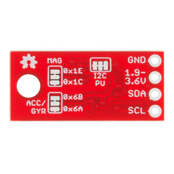
well designed, easy to use, very compact. I also like the design of the solder/cut pads for i2c pull-ups and address
1 of 2 found this helpful:
For sorry the first device i buy from spark fun and let me down
Only its accelerometer and gyroscope is very accurate in getting rotating around X and Y but the heading of compass is really bad.
It makes me very crazy because of false readings of manometer as it can be effected by any close magnetic filed and give you completely wrong values.
But the good thing is its small size, but i won't buy it again if i want to make application depending on compass.
Sorry to hear about the issue with the 9 DoF sensor stick! Have you contacted our technical support @ techsupport@sparkfun.com? They're usually very good at helping figure out if a board is behaving out of scope and troubleshooting problems that may be going on within a setup.
0 of 1 found this helpful:
Horrible design
I get its cheap, but this stick broke within a couple minutes of use. The fiberglass is no more than 0.030" thick, and I would not be surprised if a little bending load broke the joints on the chip.
Overall disappointed.
simple and efficient
very easy to use on a arduino prototyping board
Accurate and easy to use
Works extremely well and gives accurate readings. Could use more in-depth documentation instead of needing to read library code.
9DoF Sensor Stick, need help with heading indication
Hooked this unit up to my Red Board and can't seem to get the heading indication to work much at all. I'm looking to get some help from tech support after Cyber Monday but if anyone has recommendations regarding magnetometer calibration and if any code correction is needed I'd love to hear form you. Heading seems to be mostly unresponsive to z-axis orientation.
I am able to load the Basic_I2C Arduino sketch and I am receiving data. The only data I actually need is the heading and it seems that the magnetometer doesn't work very well. I only get a heading of about 190 degrees to 215 degrees when I rotate the stick 360 degrees. I even tried severing the default magnetometer address to use the secondary with no luck.
Could you explain how you set up the FreeIMU software (https://github.com/mjs513/FreeIMU-Updates) for the calibration demo you showed on the video in this page? I am currently trying to set this software up for this sensor stick but I am running with some problems with the GUI.
Given the on board processing, what is the time delay between actual change in motion/position and when it shows in the signals?
Is it possible to configure it to use interrupts over I2C?
Does it need a logic level converter to work with an arduino uno R3? Also, which are the VOL, VOH, VIL and VIH from this board?
No, it doesn't need a logic converter. I've tested it on a 5V Redboard and because I2C uses open drains on the I2C lines, you won't damage the controller using 5V logic. Just be sure to use 3.3V as the power source.
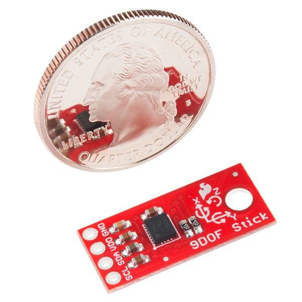
Can you please post the actual dimensions of the board? A photo of the board next to a quarter on its side gives a general idea, though not as good as your usual method of depicting devices next to a ruler. Neither, however, is quite so accurate (nor so easy to list) as the actual dimensions. If one has these, the photos are superfluous.
Sorry about that. Alex's dimensions should be correct, although you can always check the Eagle files as well. While this is a pretty simple board the Eagle files work much better for things like finding the distance between the edge and a mounting hole, or a connector, etc. So if you ever need dimensions that is another option.
Sorry about that 23Arts. The board dimensions are 0.400" wide by 0.900" in legnth.
Is the silkscreen reference frame correct? It's not a right hand reference frame, which is quite irregular...
Yes the silk reference is correct with the exception of the X-Axis on the magnetometer. For some reason the X-Axis is reversed, but both the Y and Z are axes as well as the other 6 degrees match the silk.
How does this compare to the MPU-9250 https://www.sparkfun.com/products/13762 (looks like it is the same price)?
Both boards are very similar. The main difference comes from the magnetometer. In short, the MPU-9250 can measure stronger magnetic fields than the Sensor Stick. The MPU-2950 has a sensitivity of ±48 Gauss, while the LSM9DS1 (used on the Sensor Stick) has a configurable sensitivity of ±4/±8/±12/±16 Gauss. I believe both return a 16-bit value, so while the MPU-2950 can sense a higher magnetic field, the sensor stick is more sensitive.
I had the old sensor stick with the LSM9DS0, which unfortunately broke recently. Can I replace it with this board and use the same libraries?
Unfortunately not. But we do have a hookup guide and the Arduino libary should make updating your code a little easier.
So where is this free IMU firmware? I have one of these on you larger board but have not been able to get my software to a point where the data is accurate enough for my application. Gyro drift is my main problem. I have tried implementing some filters but have not been successful yet.
RTIMULib should also work with this board connected to a Linux box (Pi, Edison, etc.). Mr. Google will tell you where it is.
The code is here, I think: https://github.com/sparkfun/SparkFun_LSM9DS1_Particle_Library/tree/master/firmware